
Introduction
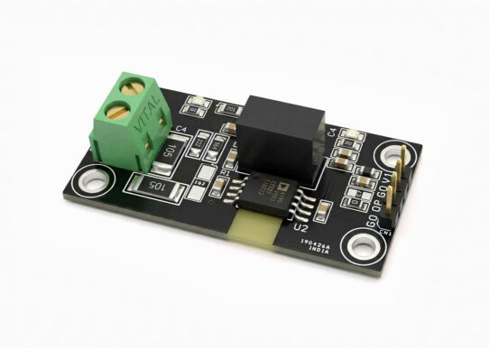
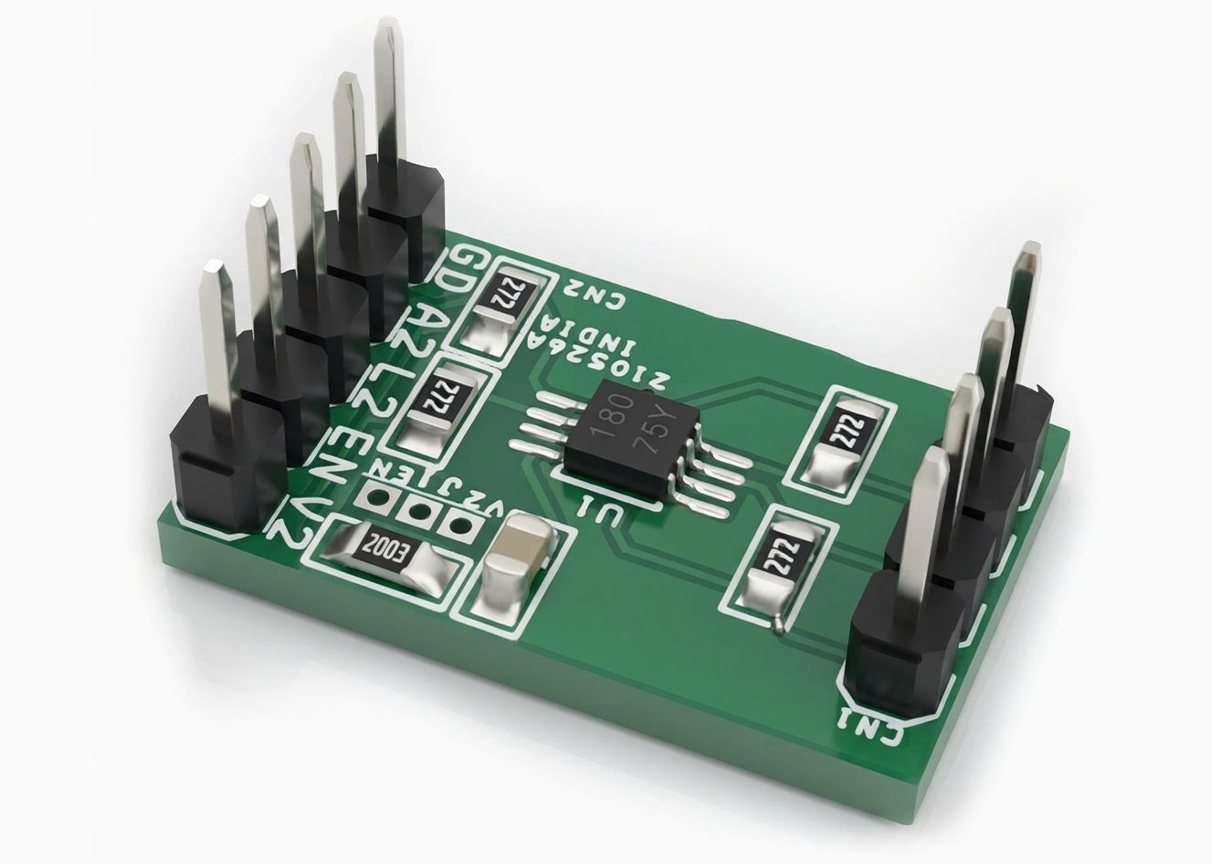
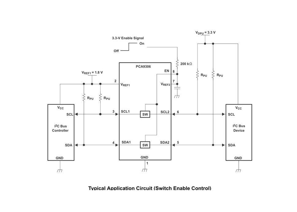
The project is built using PCA9306 IC which is dual bidirectional I2C and SMBus voltage-level translator with an enable (EN) input, and is operational from 1.2-V to 3.3-V VREF1 and 1.8-V to 5.5-V VREF2. The PCA9306 device allows bidirectional voltage translations between 1.2 V and 5 V, without the use of a direction pin. The low ON-state resistance (RON) of the switch allows connections to be made with minimal propagation delay. When EN is high, the translator switch is ON, and the SCL1 and SDA1 I/O are connected to the SCL2 and SDA2 I/O, respectively, allowing bidirectional data flow between ports. When EN is low, the translator switch is off, and a high-impedance state exists between ports. In addition to voltage translation, the PCA9306 device can be used to isolate a 400-kHz bus from a 100-kHz bus by controlling the EN pin to disconnect the slower bus during fast-mode communication.
Features
- 2-Bit bidirectional translator for SDA and SCL lines in mixed-mode I2C Applications
- I2C and SMBus compatible
- Less than 1.5-ns maximum propagation delay to
- accommodate standard-mode and fast-mode I2C
- devices and multiple controllers
- Allows voltage-level translation between– 1.2-V VREF1 and 1.8-V, 2.5-V, 3.3-V, or 5-V VREF2– 1.8-V VREF1 and 2.5-V, 3.3-V, or 5-V VREF2– 2.5-V VREF1 and 3.3-V or 5-V VREF2– 3.3-V VREF1 and 5-V VREF2
- Provides bidirectional voltage translation with no direction pin
- Low 3.5-Ω ON-state resistance between input and
- Output ports provide less signal distortion
- Open-drain I2C I/O ports (SCL1, SDA1, SCL2, and SDA2)
- 5-V Tolerant I2C I/O ports to support mixed-mode signal operation
- High-impedance SCL1, SDA1, SCL2, and SDA2 pins for EN = low
- Lockup-free operation for isolation when EN = low
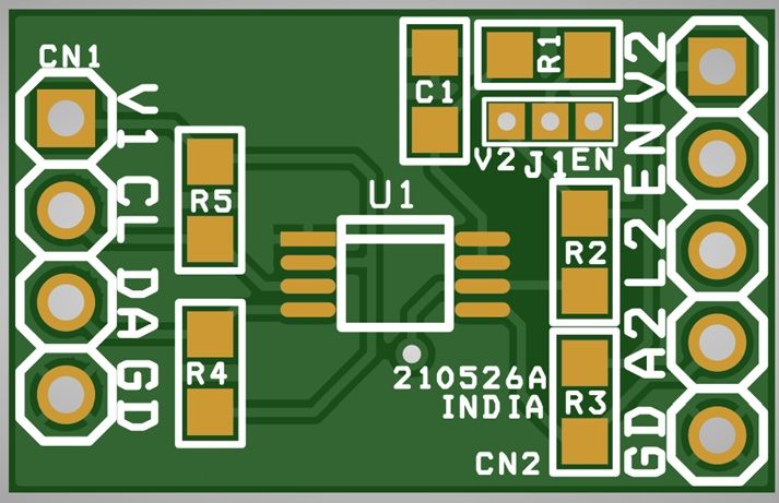
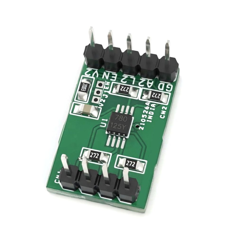
- PCB DIMENSIONS 21.11 x 13.34 mm
Schematic
Connections
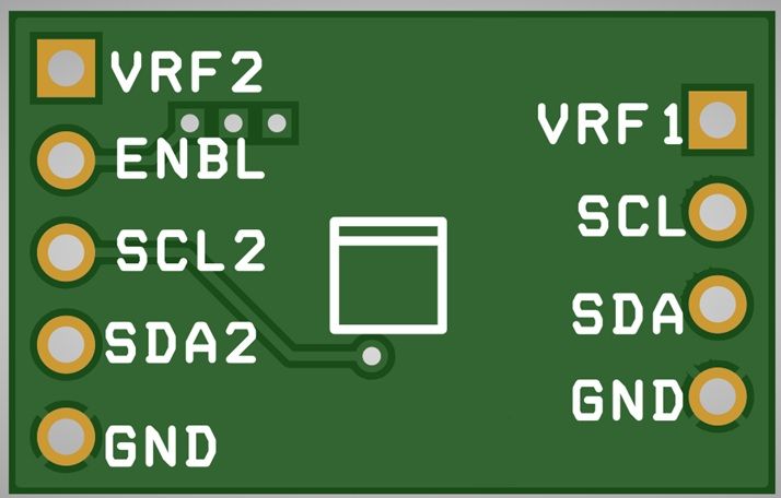
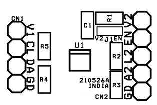
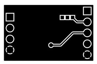
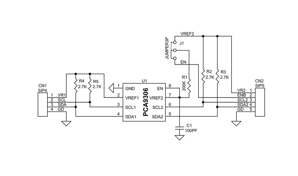
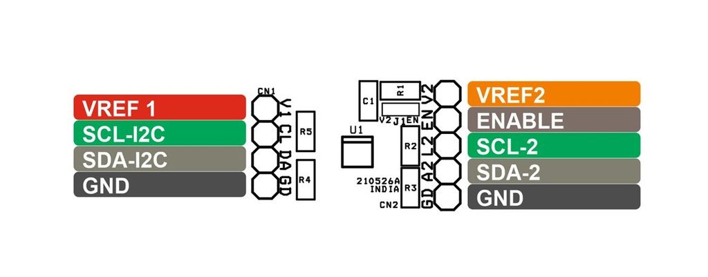
- CN1: Pin 1 = VREF1, Pin 2 = SCL-I2C, Pin 3 = SDA-I2C, Pin 4 = GND
- CN2: Pin 1 = VREF2, Pin 2 = Enable, Pin 3 = SCL2, Pin 4 = SDA, Pin 5 = GND
- J1: Jumper Enable/VREF2 Selection
Part List
| NO. | QNTY. | REF. | DESC. | MANUFACTURER | SUPPLIER | SUPPLIER PART NO |
|---|---|---|---|---|---|---|
| 1 | 1 | CN1 | 4 PIN MALE HEADER PITCH 2.54MM | WURTH | DIGIKEY | 732-5317-ND |
| 2 | 1 | CN2 | 5 PIN MALE HEADER PITCH 2.54MM | WURTH | DIGIKEY | 732-5318-ND |
| 3 | 1 | C1 | 100PF/50V CERAMIC SMD SIZE 0805 | YAGEO/MURATA | DIGIKEY | |
| 4 | 1 | J1 | JUMPER3P SOLDER TYPE | YAGEO/MURATA | DIGIKEY | |
| 5 | 1 | R1 | 200K 1% SMD SIZE 0805 | YAGEO/MURATA | DIGIKEY | |
| 6 | 4 | R2,R3,R4,R5 | 2.7K 5% SMD SIZE 0805 | YAGEO/MURATA | DIGIKEY | |
| 7 | 1 | U1 | PCA9306 | NXP | DIGIKEY | 568-PCA9306DC1ZCT-ND |
PCA9306 IC
Operating Features and Benefits
The PCA9306 device is a dual bidirectional I2C and SMBus voltage-level translator with an enable (EN) input and operates without use of a direction pin. The voltage supply range for VREF1 is 1.2 V to 3.3 V and the supply range for VREF2 is 1.8 V to 5.5 V. The PCA9306 device can also be used to run two buses, one at 400-kHz operating frequency and the other at 100-kHz operating frequency. If the two buses are operating at different frequencies, the 100-kHz bus must be disconnected by using the EN pin when the 400-kHz operation of the main bus is required. If the controller is running at 400 kHz, the maximum system operating frequency may be less than 400 kHz because of the delays added by the level shifter. In I2C applications, the bus capacitance limit of 400 pF restricts the number of devices and bus length. The capacitive load on both sides of the PCA9306 device must be taken into account when approximating the total load of the system, ensuring the sum of both sides is under 400 pF. Both the SDA and SCL channels of the PCA9306 device have the same electrical characteristics, and there is minimal deviation from one output to another in voltage or propagation delay. This is a benefit over discrete transistor voltage-translation solutions, because the fabrication of the switch is symmetrical. The translator provides excellent ESD protection to lower-voltage devices and at the same time protects less-ESD-resistant devices.
PCB View