
Introduction
This project is built using the A1333 chip, a high-precision 360° contactless angle sensor that provides high-resolution angular position data using advanced Circular Vertical Hall (CVH) magnetic sensing technology. The sensor is designed to deliver accurate and reliable rotational position measurement over a full 0° to 360° range. The A1333 features an integrated System-on-Chip (SoC) architecture that combines a CVH sensing front end, digital signal processing, and configurable motor commutation (UVW) or incremental encoder outputs (A, B, I). This enables the device to be easily integrated into motion control, automotive, and industrial applications requiring precise rotational feedback. The chip also incorporates on-chip EEPROM memory capable of up to 100 read/write cycles, allowing flexible end-of-line programming and calibration of sensor parameters without additional external memory.
With its high speed, excellent accuracy, and contactless magnetic sensing operation, the A1333 is ideal for demanding automotive and industrial applications such as Electronic Power Steering (EPS), rotary PRNDL systems, throttle position sensing, motor control systems, robotics, and precision angular measurement applications.
Features
- Operating supply voltage range from 4.0 to 16.5 V
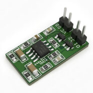
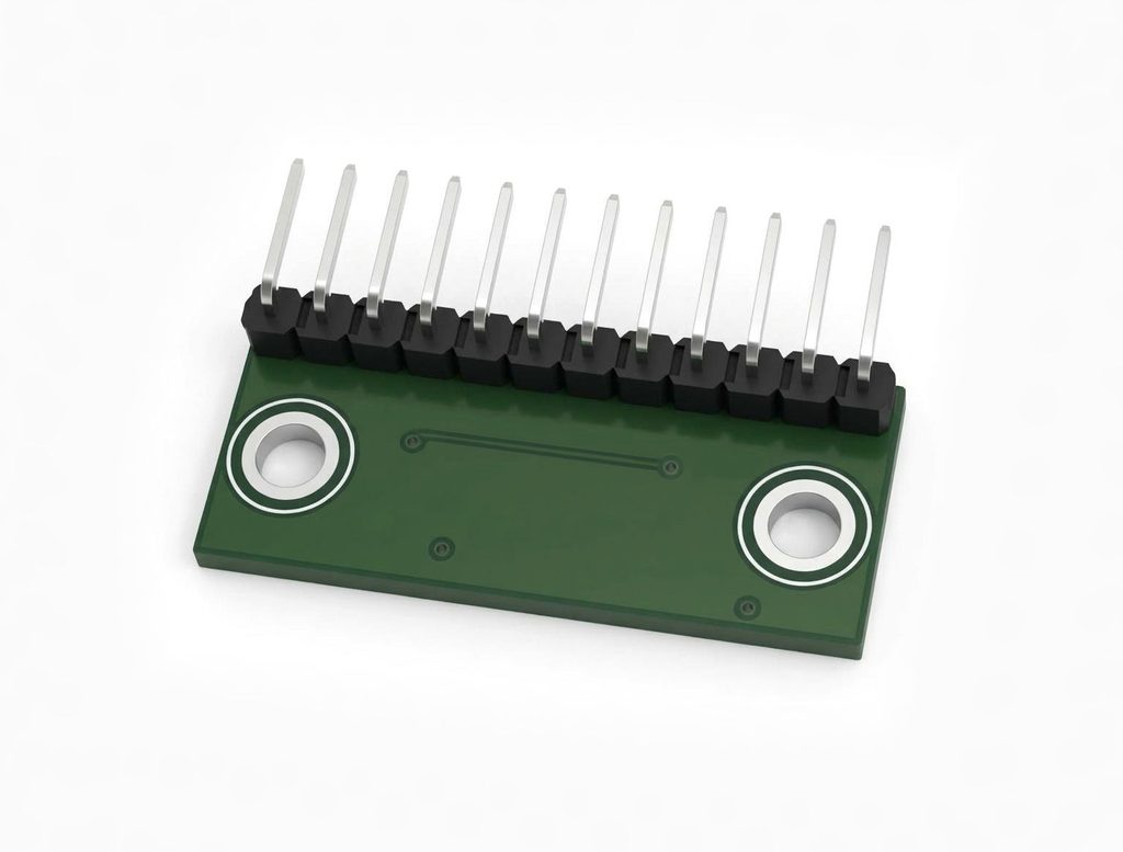
- Header Connector For Power and Digital Interface
- Contactless 0° to 360° angle sensor IC, for angular position, rotational speed, and direction measurement
- On-chip EEPROM for storing calibration parameters
- Single-bit error correction, dual-bit error detection through the use of error correction control (ECC)
- Supports harsh operating conditions required for automotive and industrial applications, including direct connection to 12 V battery
- ABI/UVW output provides high resolution, low latency, and PWM for initial position
- Output resolution on ABI and UVW are selectable
- Multiple programming/configuration formats supported
- The system can be completely controlled and programmed over SPI, including EEPROM writes
- For system with limited pins available, writing and reading can be performed over VCC and PWM pins. This allows configuring the EEPROM in production line for a device with only ABI/UVW and PWM pins connected.
- Capable of sensing magnet rotational speeds targeting 12-bit effective resolution with 900G field
- Circular vertical Hall (CVH) technology provides a single-channel sensor system supporting operation across a wide range of air gaps
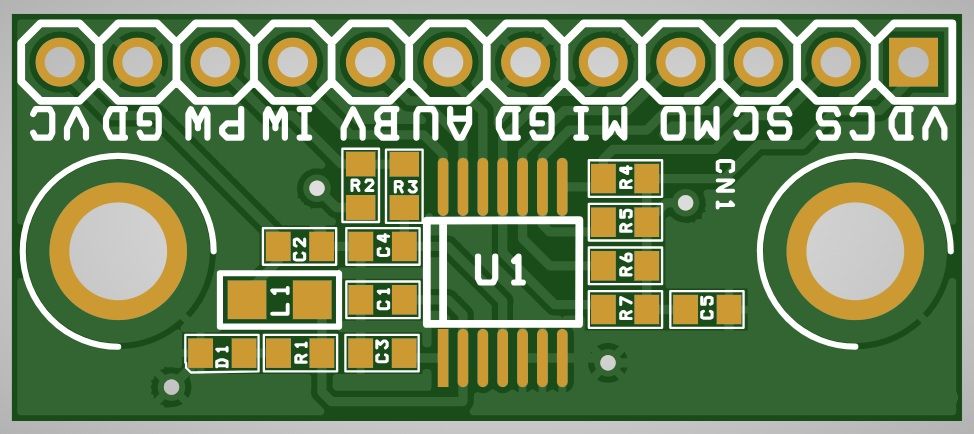
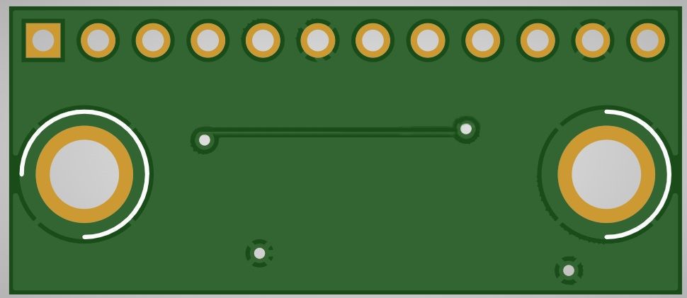
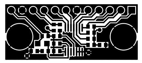
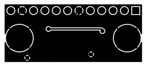
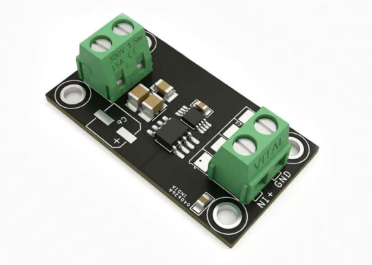
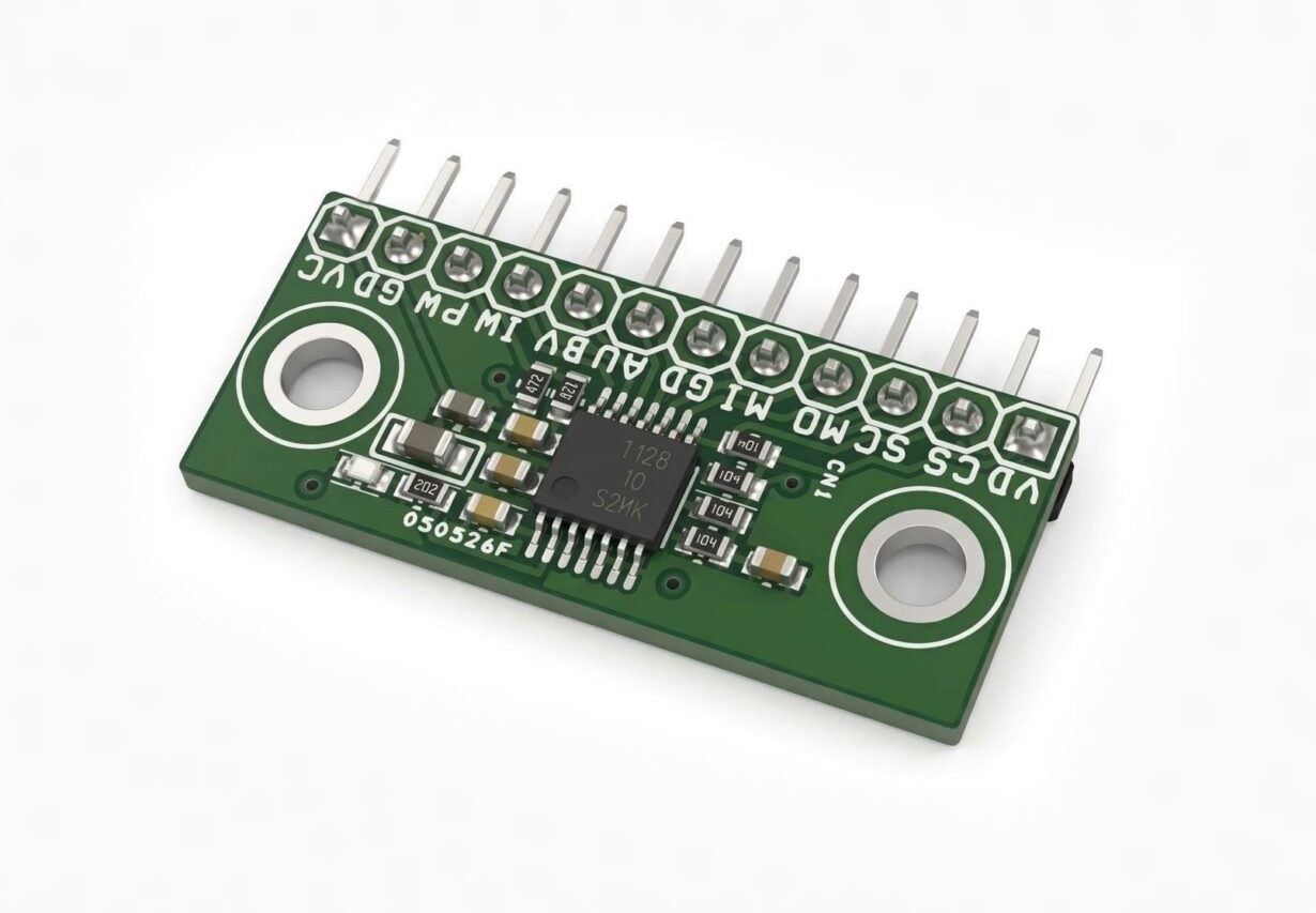
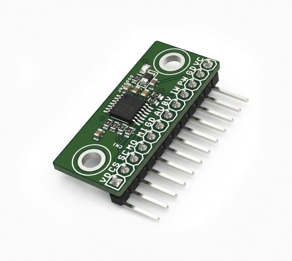
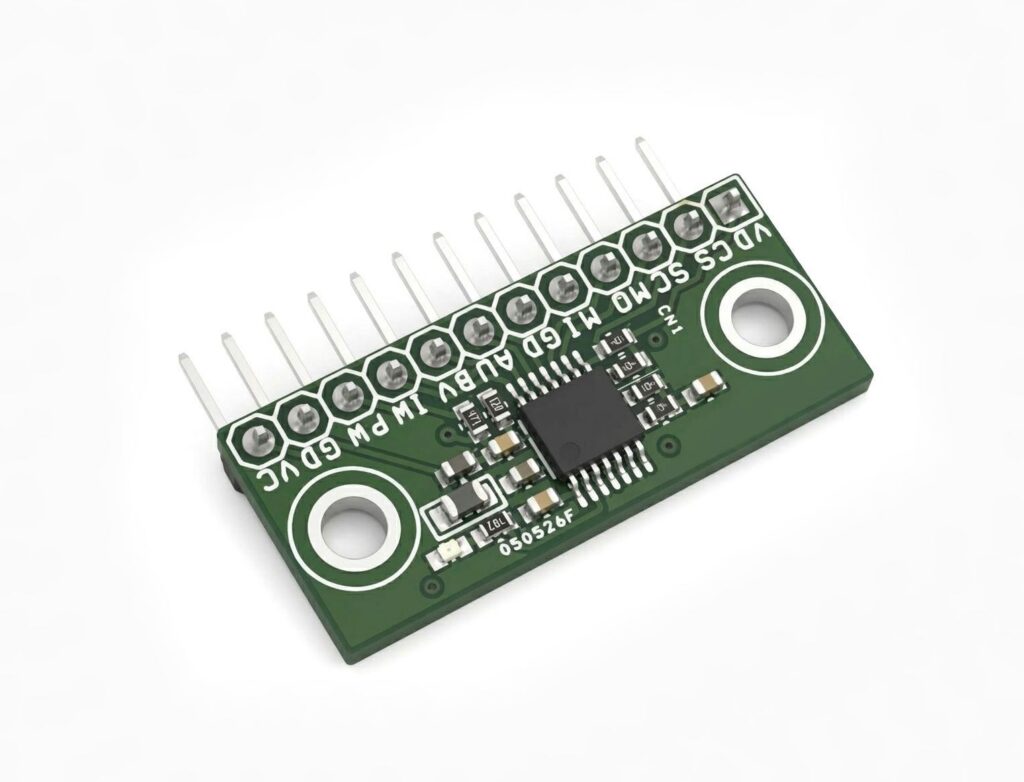
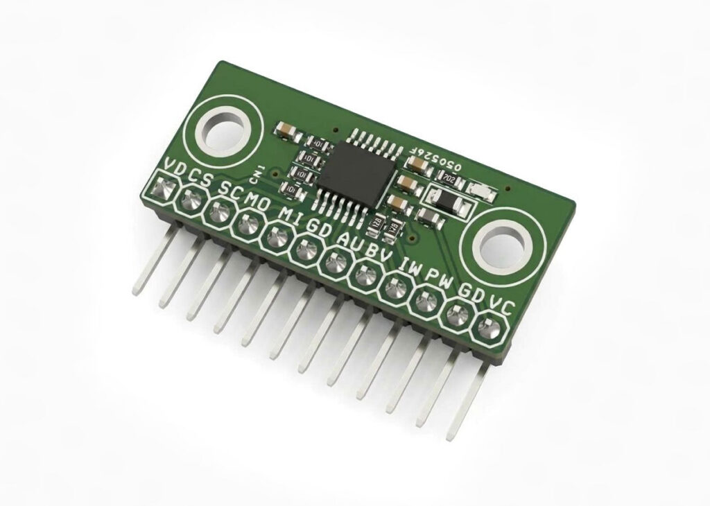
- PCB Dimensions 31.12 x 13.34 mm
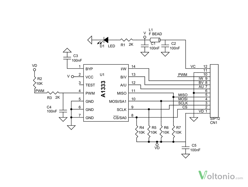
Schematic
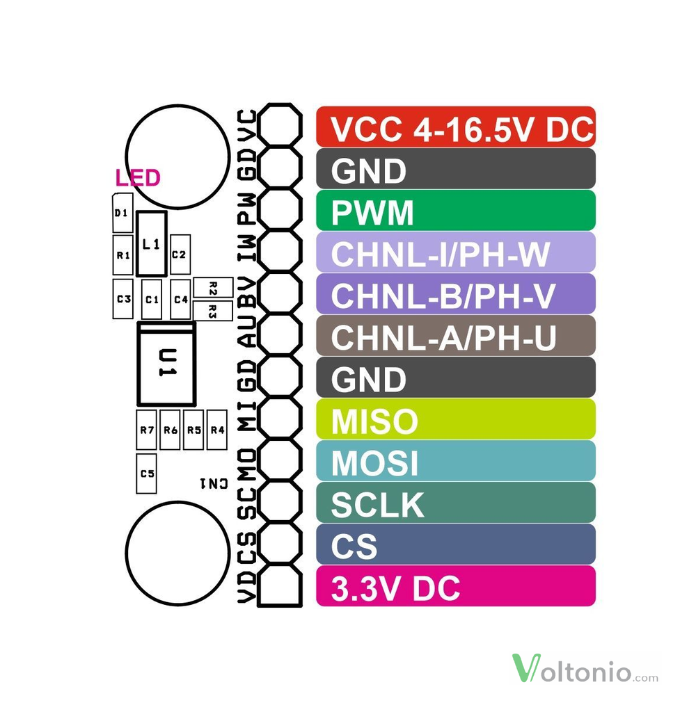
Connections
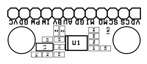
- CN1: Pin 1 = 3.3V Pull Up Power for Digital I/O, Pin 2 = CS/SA0, Pin 3 = SCLK, Pin 4 = MOSI, Pin 5 = MISO, Pin 6 = GND, Pin 7 = Channel A or Phase U, Pin 8 = Channel B or Phase V, Pin 9 = Channel I or Phase W, Pin 10 = PWM, Pin 11 = GND, Pin 12 = VCC 4V to 16.5V
- D1: Power LED
Part List
| NO. | QNTY. | REF. | DESC. | MANUFACTURER | SUPPLIER | SUPPLIER PART NO |
|---|---|---|---|---|---|---|
| 1 | 1 | CN1 | 12 PIN MALE HEADER PITCH 2.54MM | WURTH | DIGIKEY | 732-5323-ND |
| 2 | 5 | C1,C2,C3,C4,C5 | 100nF/25V CERAMIC SMD SIZE 0603 | YAGEO/MURATA | DIGIKEY | |
| 3 | 1 | D1 | LED SMD SIZE 0603 | WURTH | DIGIKEY | 732-4979-1-ND |
| 4 | 1 | L1 | 600OHMS SMD SIZE 0805 | LAIRD | DIGIKEY | 240-2399-1-ND |
| 5 | 2 | R1,R3 | 2K 5% SMD SIZE 0603 | YAGEO/MURATA | DIGIKEY | |
| 6 | 5 | R2,R4,R5,R6,R7 | 10K 5% SMD SIZE 0603 | YAGEO/MURATA | DIGIKEY | |
| 7 | 1 | U1 | A1333 FOR 5V I/O | ALLEGRO | DIGIKEY | 620-A1333LLETR-5-TCT-ND |
| 8 | 1 | U1 | A1333 FOR 3.3V I/O | ALLEGRO | DIGIKEY | 620-A1333LLETR-TCT-ND |
A1333 Angle Sensor
Overview – Angle Measurement, PWM, and ABI Encoder Outputs
Overview The A1333 is a rotary position Hall-sensor-based device in a surface-mount package, providing solid-state consistency, reliability, and supporting a wide variety of automotive applications. The Hall-sensor-based device measures the direction of the magnetic field vector through 360° in the x-y plane (parallel to the branded face of the device) and computes an angle measurement based on the actual physical reading, as well as any internal parameters that have been set by the user. The output is used by the host microcontroller to provide a single channel of target data.
This device is an advanced, programmable system-on-chip (SoC). Each integrated circuit includes a circular vertical Hall (CVH) analog front end, a high-speed sampling analog-to-digital converter (ADC), digital filtering, digital signal processing (which includes two separate signal paths), SPI, PWM, motor commutation outputs (UVW), and encoder outputs (A, B, I). Offset, filtering, and diagnostic adjustment options are available in the A1333. These options can be configured in onboard EEPROM, providing a wide range of sensing solutions in the same device.
Device performance can be optimized by enabling individual functions or disabling them in EEPROM to minimize latency.
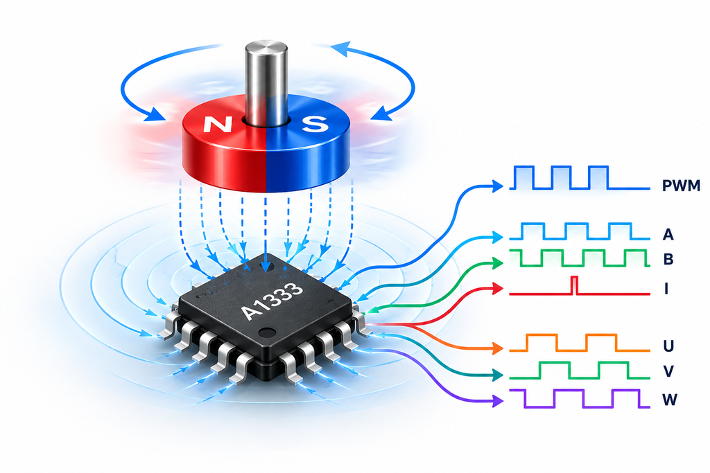
Angle Measurement the IC features two digital signal paths. The main signal path uses a PLL to generate high-resolution, low-latency angle readings. A secondary, lower-power signal path (referred to as the ZCD path) is used for turns-counting, magnetic-field measurement, and diagnostic comparison.
The A1333 is capable of tracking magnet position at high speed. Performance up to 12,000 rpm has been verified by testing. Operation up to 30,000 rpm has been verified via design simulation. The A1333 has a typical refresh rate of 1 MHz Angle is represented as either a 12- or 15-bit value, based on the register address accessed. PWM Output the A1333 provides a pulse-width-modulated open-drain output, with the duty cycle (DC) proportional to measured angle.
The PWM duty cycle is clamped at 5% and 95% for diagnostics purposes. A 5% DC corresponds to 0°; a 95% DC corresponds to 360°. Incremental Output Interface (ABI). The A1333 offers an incremental output mode in the form of quadrature A/B and index outputs to emulate an optical or mechanical encoder.
The A and B signals toggle with a 50% duty cycle (relative to angular distance, not necessarily time) at a frequency of 2N cycles per magnetic revolution, giving a cycle resolution of (360 / 2N) degrees per cycle, where N is set by the RESOLUTION_PAIRS field in EEPROM; see Table 2. B is offset from A by ¼ of the cycle period. The “I” signal is an index pulse that occurs once per revolution to mark the zero (0) angle position.
PCB View