



Introduction
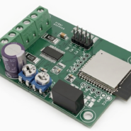
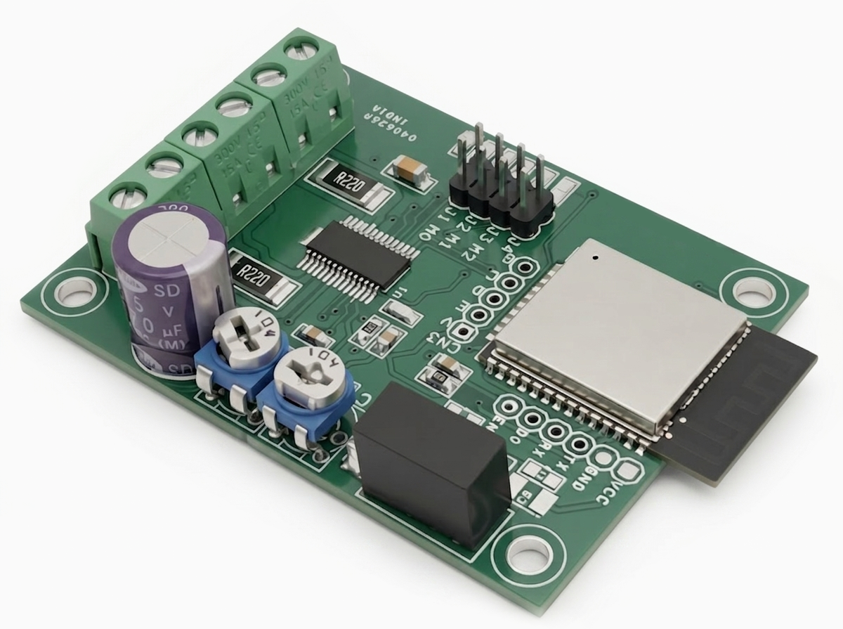
This Wi-Fi Stepper Motor Driver enables remote control of a bipolar stepper motor over a wireless network. The project is based on the ESP32 Wi-Fi microcontroller and the BD63731EFV stepper motor driver IC, providing a compact and reliable solution for motion control applications.
The driver operates from a 24 VDC power supply and is capable of driving bipolar stepper motors with output currents of up to 3A. The BD63731EFV supports multiple micro-stepping modes, allowing smooth and precise motor operation while reducing vibration and audible noise.
Features
- Motor Supply 24V DC
- Rated Output Current 3.0 A
- Low ON Resistance DMOS Output
- CLK-IN Drive Mode
- PWM Constant Current (other oscillation)
- Built-in Spike Noise Cancel Function (external noise filter is unnecessary)
- FULL STEP (2 types), HALF STEP (2 types),
- QUARTER STEP (2 types), 1/8 STEP, 1/16 STEP Functionality
- Freely Timing Excitation Mode Switch
- Current Decay Mode Switch (linearly variable SLOW/FAST DECAY ratio)
- Normal Rotation & Reverse Rotation Switching Function
- Power Save Function (PS Jumper J4)
- Built-in Logic Input Pull-down Resistor
- Power-on Reset Function
- Thermal Shutdown Circuit (TSD)
- Over-current Protection Circuit (OCP)
- Under Voltage Lock Out Circuit (UVLO)
- Over Voltage Lock Out Circuit (OVLO)
- Protects Against Malfunction when Power Supply is Disconnected (Ghost Supply Prevention Function)
- Adjacent Pins Short Protection
- Microminiature, Ultra-thin and High Heat-radiation (exposed metal type) Package
- 4 x 3 mm PCB Mounting Holes
- PCB Dimensions 60.96 x 45.09 mm
The ESP32 interfaces directly with the stepper driver using dedicated control signals:
- GPIO21 → Enable (EN)
- GPIO22 → Direction (DIR)
- GPIO23 → Step Pulse (STEP)
An onboard isolated DC-DC converter generates an isolated 3.3V supply for the ESP32 and associated low-voltage logic circuitry from the 24VDC input. This isolated power supply improves system reliability by reducing electrical noise and providing enhanced protection between the motor power stage and the control electronics.
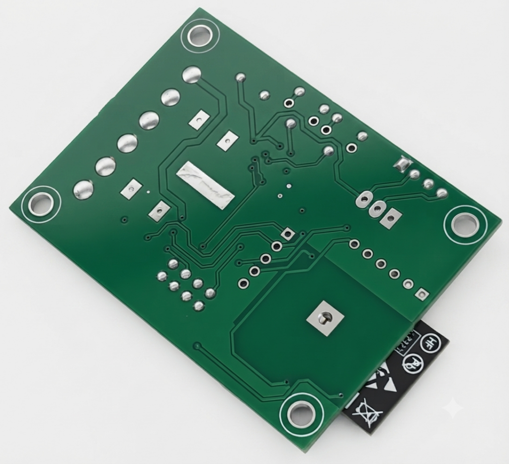
The combination of wireless connectivity, high-current motor drive capability, micro-stepping support, and isolated power makes this module ideal for industrial automation, robotics, CNC machines, laboratory equipment, and other remote motion control applications.
Schematic
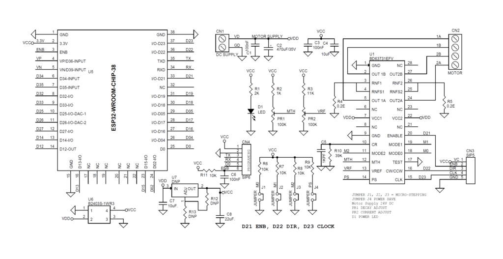
Connections
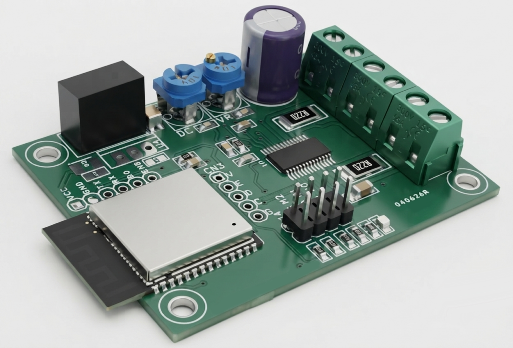
- CN1: Pin 1 = VDD 24V DC, Pin 2 = GND
- CN2: Stepper Motor, Pin 1 = Motor 1A, Pin 2 = Motor 1B, Pin 3 = Motor 2B, Pin 4 = Motor 2A
- D1: Power LED
- PR1: Trimmer Pot Decay Adjust
- PR2: Trimmer Pot Current Adjust
- CN4: ESP32 Programming PORT
- J1, J2, J3: Jumper = Micro Stepping Configuration
- J4: Motor Standby (High for Normal Operation)
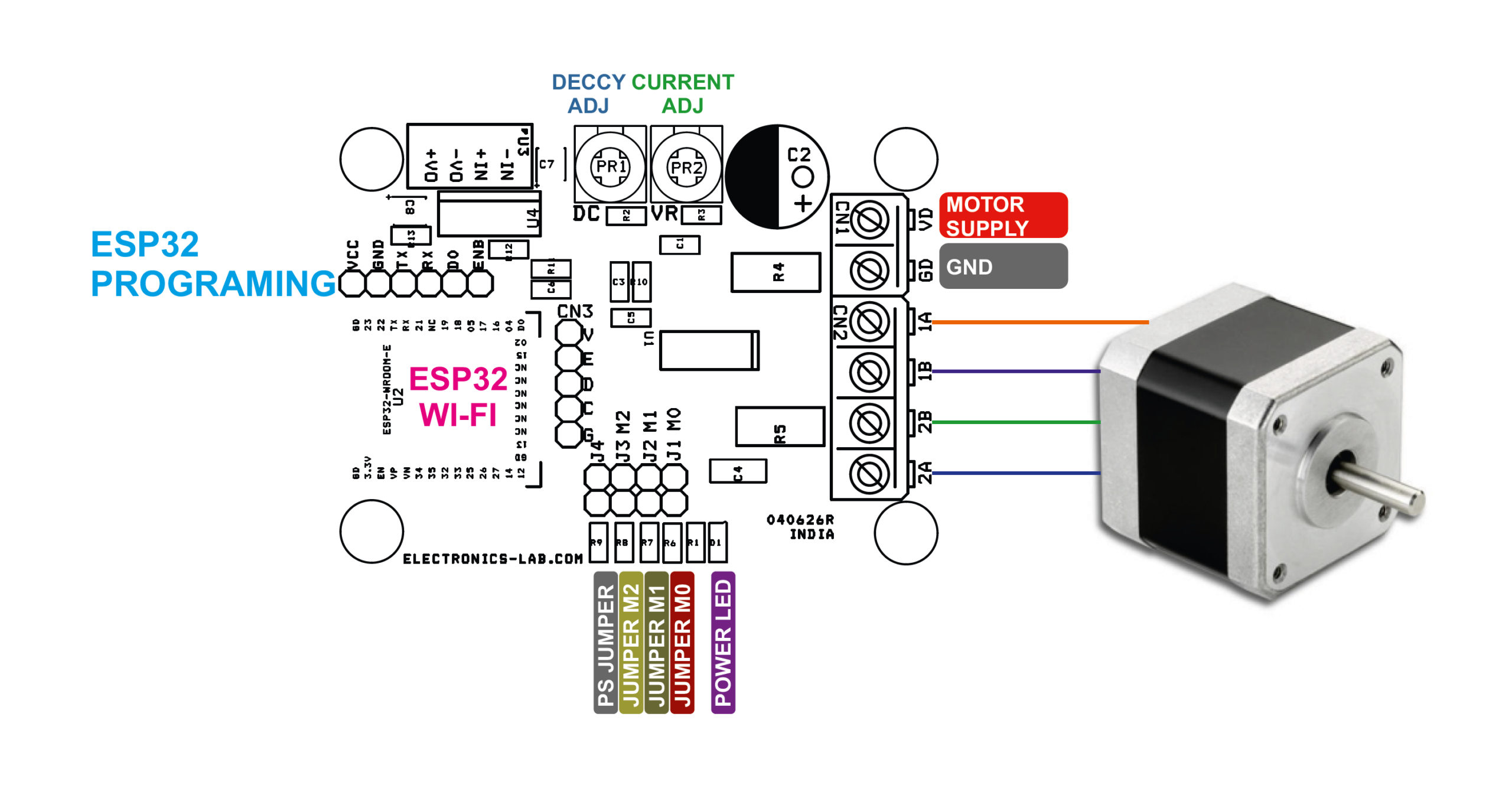
Parts List
| NO. | QNTY. | REF. | DESC. | MANUFACTURER | SUPPLIER | SUPPLIER PART NO |
|---|---|---|---|---|---|---|
| 1 | 2 | CN1,CN2 | 2 PIN SCREW TERMINAL PITCH 5.08MM | PHOENIX | DIGIKEY | 277-1247-ND |
| 2 | 4 | SHUNT | SHUNT FOR J1, J2, J3, J4 | SULLINS CONNECT | DIGIKEY | S9001-ND |
| 3 | 1 | CN3 | DNP | DIGIKEY | ||
| 4 | 1 | CN4 | 6 PIN MALE HEADER PITCH 2.54MM | WURTH | DIGIKEY | 732-5319-ND |
| 5 | 3 | C1,C3,C6 | 100nF/50V CERAMIC SMD SIZE 0805 | YAGEO/MURATA | DIGIKEY | |
| 6 | 1 | C2 | 470uF/35V | RUBYCON | DIGIKEY | 1189-1280-ND |
| 7 | 2 | C7 | 10uF/35V CERAMIC SMD SIZE 1210 | YAGEO/MURATA | DIGIKEY | |
| 8 | 1 | C5 | 1KPF/50V CERAMIC SMD SIZE 0805 | YAGEO/MURATA | DIGIKEY | |
| 9 | 1 | C8 | 22uF/25V CERAMIC SMD SIZE 1210/1206 | YAGEO/MURATA | DIGIKEY | |
| 10 | 1 | D1 | LED RED SMD SIZE 0805 | OSRAM | DIGIKEY | 475-1278-1-ND |
| 11 | 4 | J1,J2,J3,J4 | 2 PIN MALE HEADER PITCH 2.54MM | WURTH | DIGIKEY | 732-5315-ND |
| 12 | 2 | PR1,PR2 | 100K TRIMMER POT 6x6MM | BORNS INC | DIGIKEY | 3362P-104LF-ND |
| 13 | 1 | R1 | 2K 1% SMD SIZE 0805 | YAGEO/MURATA | DIGIKEY | |
| 14 | 1 | R2 | 1K % SMD SIZE 0805 | YAGEO/MURATA | DIGIKEY | |
| 15 | 1 | R3 | 11K 1% SMD SIZE 0805 | YAGEO/MURATA | DIGIKEY | |
| 16 | 2 | R4,R5 | 0.2E/2W SMD SIZE 2512 | BOURNS INC | DIGIKEY | CRM2512-FX-R200ELFCT-ND |
| 17 | 5 | R6,R7,R8,R9,R11 | 10K 5% SMD SIZE 0805 | YAGEO/MURATA | DIGIKEY | |
| 18 | 1 | R10 | 39K 5% SMD SIZE 0805 | YAGEO/MURATA | DIGIKEY | |
| 19 | 3 | U7,R12,R13 | DNP | |||
| 20 | 1 | U1 | BD63731EFV | ROHM | DIGIKEY | 846-BD63731EFV-E2CT-ND |
| 21 | 1 | U5 | ESP32-WROOM CHIP | ESP | DIGIKEY | 1965-ESP32-WROOM-32E-N4CT-ND |
| 22 | 1 | U6 | B2403S-1WR3 | MORNSUN | DIGIKEY | 2725-B2403S-1WR3-ND |
| 23 | 1 | C4 | 10uF/35V CERAMIC SMD SIZE 1206 | YAGEO/MURATA | DIGIKEY | |
Power Supply
This module is designed to operate from a 24 VDC power supply. The onboard isolated DC-DC converter (U6) converts the 24 V input into an isolated 3.3 VDC supply for the ESP32 microcontroller and associated logic circuitry.
As an alternative power option, the PCB also provides footprints for an LM317 voltage regulator (U7) along with output-setting resistors R12 and R13. If the LM317 regulator is installed, do not populate the DC-DC converter (U6). Only one of these power supply options should be used at a time.
Bipolar Stepper Motor Driver
The bipolar stepper motor driver is based on the BD63731EFV high-performance stepper motor driver IC, a low-power PWM current-controlled driver designed for efficient and precise motor control. The module operates from a 24 VDC power supply and is capable of delivering up to 3.0 A output current, making it suitable for a wide range of bipolar stepper motors.
The driver uses a CLK-IN interface, requiring only STEP (CLK) and DIRECTION (DIR) input signals for motor control. It supports multiple excitation (micro-stepping) modes, including:
- Full-Step (2 modes)
- Half-Step (2 modes)
- Quarter-Step (2 modes)
- 1/8-Step
- 1/16-Step
These micro-stepping modes are generated using the driver’s built-in DAC, enabling smooth, accurate, and low-noise motor operation.
The BD63731EFV also provides flexible current decay control. The ratio of Slow Decay to Fast Decay can be adjusted over a wide range, allowing the current waveform to be optimized for different motors and operating conditions. This results in improved torque characteristics, reduced vibration, and quieter operation.
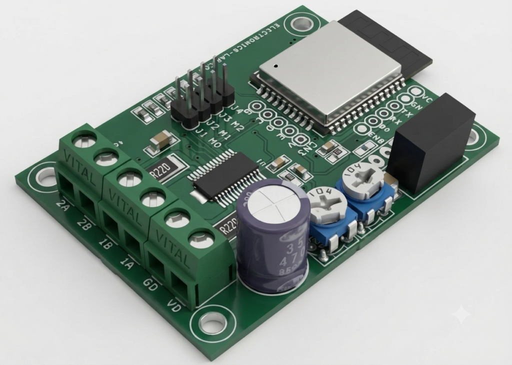
The driver requires only a single power supply, simplifying the overall system design while reducing component count and PCB complexity. With its high output current capability, advanced current control, and flexible micro-stepping options, this driver is an excellent choice for CNC machines, robotics, industrial automation, 3D printers, and other precision motion control applications.
Note: Refer Data sheet of BD63731EFV chip for input signals, timing chart and micro-stepping chart.
Micro-Stepping: Micro-stepping can be set using following Jumpers, J1=Mode0, J2=Mode1, J3=Mode2 (Jumper Open = High, Jumper Closed = Low)
- Mode0=Low, Mode1=Low, Mode2=Low >> Full Step A
- Mode0=High, Mode1=Low, Mode2=Low >> Half Step A
- Mode0=Low, Mode1=High, Mode2=Low >> Half Step B
- Mode0=High, Mode1=High, Mode2=Low >> Quarter Step A
- Mode0=Low, Mode1=Low, Mode2=High >> Full Step B
- Mode0=High, Mode1=Low, Mode2=High >> Quarter Step B
- Mode0=Low, Mode1=Low, Mode2=Low >> 1/8 Step
- Mode0=High, Mode1=High, Mode2=High >> 1/16 Step
Jumper J4 PS/Power Save Jumper J4
- The PS pin can make circuit in standby state and make motor output OPEN. In standby state, translator circuit is RESET (initialized) and electrical angle is initialized. When PS=L to H, be careful because there is a delay of 40 μs (Max) before it is returned from standby state to normal state and the motor output becomes ACTIVE
PR2 Trimmer Potentiometer: Motor Current Adjust = 0 to 3V
PR1 Trimmer Potentiometer: Decay Adjust
- 0 to 0.3V Slow Decay
- 0.4V to 1V Mix Decay
- 1.5V to 2V Fast Decay
- 3.1V to 3.3V Auto Decay
SLOW DECAY
The output current ripple is small and this is favourable for keeping motor torque high because the voltage between the motor coils is small and the regenerative current decreases slowly. However, an increase in the output current due to deterioration of the current control in the lower current operation in HALF STEP, QUARTER STEP, 1/8 STEP, 1/16 STEP, due to the influence of the motor reverse electromotive voltage during high pulse rate driving in the mode, the current waveform is not able to follow the change in the current limit and the distortion and motor vibration increases. Thus, this decay mode is suited to FULL STEP mode or low-pulse-rate driven HALF STEP, QUARTER STEP, 1/8 STEP or 1/16 STEP modes.
FAST DECAY
Fast decay decreases the regeneration current much more quickly than slow decay, reducing distortion of the output current waveform. However, fast decay yields a much larger output current ripple, which decreases the overall average current running through the motor. This causes two problems: first, the motor torque decreases (increasing the current limit value can help eliminate this problem, but the rated output current must be taken into consideration); and second, the power loss within the motor increases and thereby radiates more heat. If neither of these problems is of concern, then fast decay can be used for high-pulse rate HALF STEP, QUARTER STEP, 1/8 STEP or 1/16 STEP drive. Additionally, this IC allows for MIX DECAY mode/AUTO DECAY mode that can help to improve upon problems that arise from using fast or slow decay.
MIX DECAY
During current decay Switching between SLOW DECAY and FAST DECAY can improve current control without increasing the current ripple. In addition, the time ratio of SLOW DECAY and FAST DECAY can be changed by the voltage input to the MTH pin, and it is possible to achieve optimal control state for any motor. During MIX DECAY mode about chopping cycle, the first (t1 to t2) of which operates the IC in SLOW DECAY mode, and the remainder (t2 to t3) of which operates in FAST DECAY mode. However, if the output current does not reach the set current limit during the first (t1 to t2) decay period, the IC operates in fast decay mode only.
AUTO DECAY
Current control capability can still be improved without making the current ripple big by using SLOW DECAY and switches only to FAST DECAY when required. Decay mode becomes FAST DECAY only when output current reaches the set value while at minimum ON time.
Protection Circuits
Thermal Shutdown (TSD)
This IC has a built-in thermal shutdown circuit for thermal protection. When the IC’s chip temperature rises 175 °C (Typ) or more, the motor output becomes OPEN. Also, when the temperature returns to 150 °C (Typ) or less, it automatically returns to normal operation. However, even when TSD is in operation, if heat is continued to be added externally, heat overdrive can lead to destruction.
Over Current Protection (OCP)
This IC has a built-in over current protection circuit as a provision against destruction when the motor outputs are shorted each other or VCC-motor output or motor output-GND is shorted. This circuit latches the motor output to OPEN condition when the regulated current flows for 4 μs (Typ). It returns with power reactivation or a reset by the PS pin. The over current protection circuit’s only aim is to prevent the destruction of the IC from irregular situations such as motor output shorts, and is not meant to be used as protection or security for the set. Therefore, sets should not be designed to take into account this circuit’s functions. After OCP operating, if irregular situations continue and the return by power reactivation or a reset by the PS pin, then OCP operates repeatedly and the IC may generate heat or otherwise deteriorate. When the L value of the wiring is great due to the wiring being long, the motor outputs are shorted each other or VCC-motor output or motor output-GND is shorted., if the output pin voltage jumps up and the absolute maximum values can be exceeded after the over current has flowed, there is a possibility of destruction. Also, when current which is the output current rating or more and the OCP detection current or less flows, the IC can heat up to Tjmax=150 °C exceeds and can deteriorate, so current which or more the output rating should not be applied.
Under Voltage Lock Out (UVLO)
This IC has a built-in under voltage lock out function to prevent false operation such as IC output during power supply under voltage is low. When the applied voltage to the VCCX pin goes 5 V (Typ) or less, the motor output is set to OPEN. This switching voltage has a 1 V (Typ) hysteresis to prevent false operation by noise etc. Be aware that this circuit does not operate during power save mode. Also, the electrical angle is reset when he UVLO circuit operates.
Over Voltage Lock Out (OVLO)
This IC has a built-in over voltage lock out function to protect the IC output and the motor during power supply over voltage. When the applied voltage to the VCCX pin goes 32 V (Typ) or more, the motor output is set to OPEN. This switching voltage has a 1 V (Typ) hysteresis and a 4 μs (Typ) mask time to prevent false operation by noise etc. Although this over voltage locked out circuit is built-in, there is a possibility of destruction if the absolute maximum value for power supply voltage is exceeded. Therefore, the absolute maximum value should not be exceeded. Be aware that this circuit does not operate during power save mode.
Protects against malfunction when power supply is disconnected (Ghost Supply Prevention Function)
If a control signal is input when there is no power supplied to this IC, there is a function which prevents a malfunction where voltage is supplied to power supply of this IC or other IC in the set via the electrostatic destruction prevention diode from these input pins to the VCCX. Therefore, there is no malfunction of the circuit even when voltage is supplied to these input pins while there is no power supply. (Note 1) control signal=CLK, CW_CCW, MODE0, MODE1, MODE2, ENABLE, PS, MTH, VREF
Operation Under Strong Electromagnetic Field
The IC is not designed for using in the presence of strong electromagnetic field. Be sure to confirm that no malfunction is found when using the IC in a strong electromagnetic field.
Arduino Test Code
Sample Arduino code is included to verify the operation of the board. The example enables the stepper driver and rotates the motor in both directions by generating 200 Hz and 500 Hz STEP pulses.
The sample code is intended for hardware testing and demonstration purposes. Users can modify the code or develop their own firmware to implement custom motion control, speed profiles, acceleration/deceleration, and application-specific functions.
Operation
GPIO21 → ENABLE
GPIO22 → DIR
GPIO23 → STEP
At power-up:
ENABLE = HIGH
DIR = LOW
Generate 200 Hz step pulses for 5 seconds
Then:
ENABLE = LOW
Wait 1 second
Then :
ENABLE = HIGH
DIR = HIGH
Generate 500 Hz step pulses for 5 seconds
ENABLE = LOW
Wait 1 second
Then :
ENABLE = HIGH
DIR = LOW
Generate 500 Hz step poulses for 5 seconds

GO TO START LOOP

/*
  ESP32 Stepper Pulse Sequence

  GPIO21 -> ENABLE
  GPIO22 -> DIR
  GPIO23 -> STEP

  Sequence:
  1. ENABLE HIGH, DIR LOW,  200 Hz for 5 sec
  2. ENABLE LOW, wait 1 sec
  3. ENABLE HIGH, DIR HIGH, 500 Hz for 5 sec
  4. ENABLE LOW, wait 1 sec
  5. ENABLE HIGH, DIR LOW,  500 Hz for 5 sec
  6. Repeat forever
*/

const byte ENABLE_PIN = 21;
const byte DIR_PIN    = 22;
const byte STEP_PIN   = 23;

//------------------------------------------------------------
// Generate step pulses
//------------------------------------------------------------
void runStepper(uint16_t frequency, uint32_t runTime_ms)
{
  uint32_t halfPeriod_us = 1000000UL / (frequency * 2UL);
  uint32_t pulses = (uint32_t)frequency * runTime_ms / 1000UL;

  for (uint32_t i = 0; i < pulses; i++)
  {
    digitalWrite(STEP_PIN, HIGH);
    delayMicroseconds(halfPeriod_us);

    digitalWrite(STEP_PIN, LOW);
    delayMicroseconds(halfPeriod_us);
  }
}

//------------------------------------------------------------
void setup()
{
  pinMode(ENABLE_PIN, OUTPUT);
  pinMode(DIR_PIN, OUTPUT);
  pinMode(STEP_PIN, OUTPUT);

  digitalWrite(ENABLE_PIN, LOW);
  digitalWrite(DIR_PIN, LOW);
  digitalWrite(STEP_PIN, LOW);
}

//------------------------------------------------------------
void loop()
{
  //==========================================================
  // Step 1
  // ENABLE HIGH
  // DIR LOW
  // 200 Hz for 5 seconds
  //==========================================================
  digitalWrite(ENABLE_PIN, HIGH);
  digitalWrite(DIR_PIN, LOW);
  runStepper(200, 5000);

  // Disable for 1 second
  digitalWrite(ENABLE_PIN, LOW);
  delay(1000);

  //==========================================================
  // Step 2
  // ENABLE HIGH
  // DIR HIGH
  // 500 Hz for 5 seconds
  //==========================================================
  digitalWrite(ENABLE_PIN, HIGH);
  digitalWrite(DIR_PIN, HIGH);
  runStepper(500, 5000);

  // Disable for 1 second
  digitalWrite(ENABLE_PIN, LOW);
  delay(1000);

  //==========================================================
  // Step 3
  // ENABLE HIGH
  // DIR LOW
  // 500 Hz for 5 seconds
  //==========================================================
  digitalWrite(ENABLE_PIN, HIGH);
  digitalWrite(DIR_PIN, LOW);
  runStepper(500, 5000);

  // Disable for 1 second before repeating
  digitalWrite(ENABLE_PIN, LOW);
  delay(1000);

  // Loop repeats automatically
}
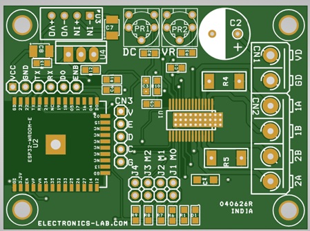
PCB View
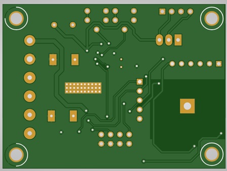
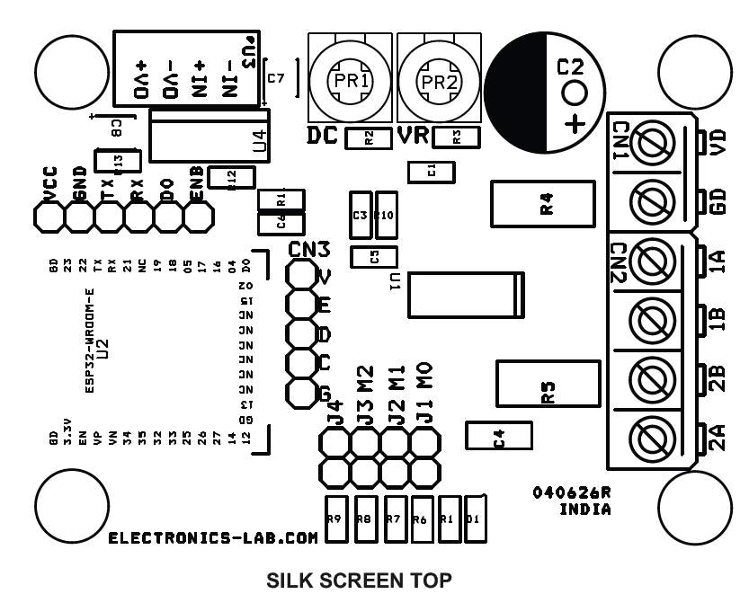
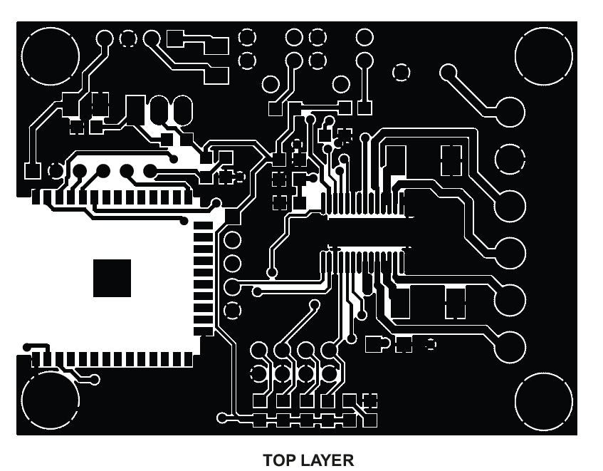
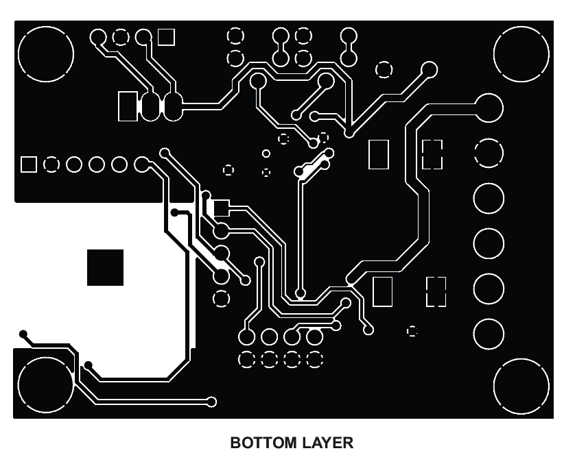







Hi, this is a comment.
To get started with moderating, editing, and deleting comments, please visit the Comments screen in the dashboard.
Commenter avatars come from Gravatar.