
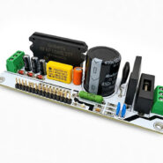
Introduction
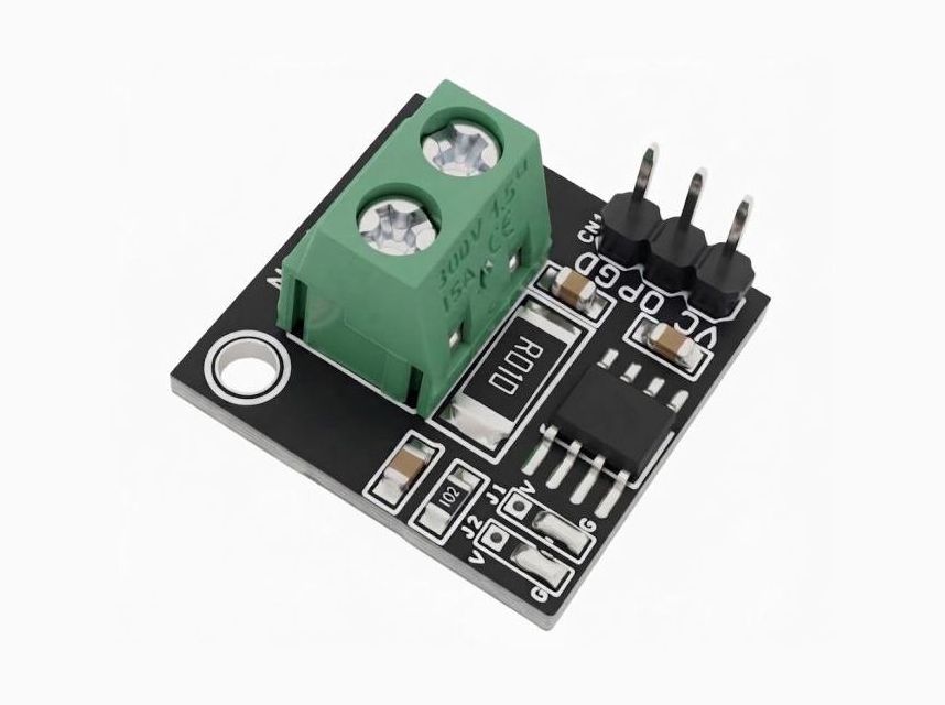
This project is a precision current-sense amplifier based on the TSC2012 current-sense amplifier IC. The device accurately measures the voltage drop across an external shunt resistor R1, enabling precise current measurement over a wide common-mode voltage range of -20 V to +70 V, independent of the supply voltage.
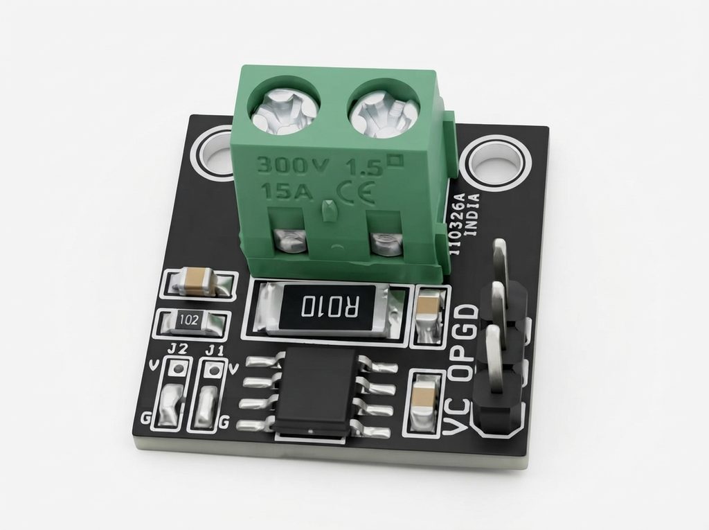
The TSC2012 features a fixed gain of 100 V/V, allowing it to accurately amplify very small shunt voltage drops. It can measure a full-scale differential input as low as 10 mV, minimizing power loss across the shunt resistor while maintaining excellent measurement accuracy.
The module operates from a single supply voltage ranging from 2.7 V to 5.5 V and is designed for reliable operation over the industrial temperature range of -40°C to +125°C, making it ideal for industrial control, motor drives, battery management systems, power supplies, and other high-side or low-side current-sensing applications.
Features
- Supply Voltage 2.7V to 5.5V
- Output 1.2V/A
- Offset Voltage: +/-200uV Max
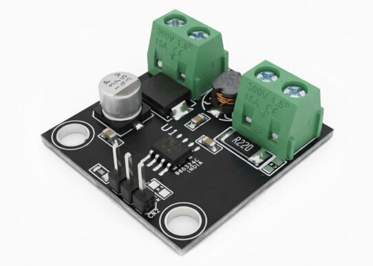
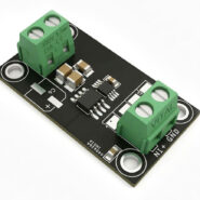
- Screw Terminal for Current Measurement
- Header Connector for Power and Output
- Two Solder Jumper on Board
- Wide Common Mode Voltage: -20V to 70V
- Gain 100V/V
- On Board Power LED
- Gain Error 0.3%
- Offset Drift 5 uV/Centigrade
- Quiescent current: 20 µA in shutdown mode
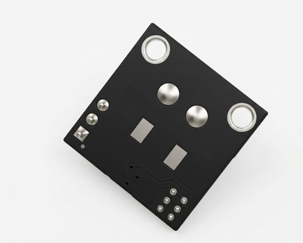
- 2 x 2 mm Mounting Holes
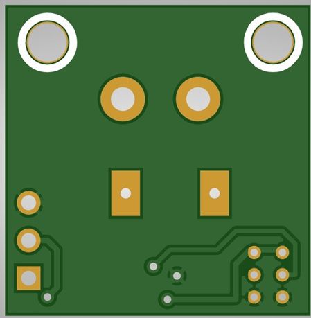
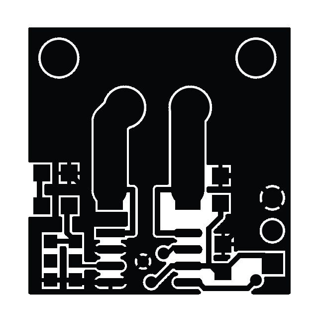
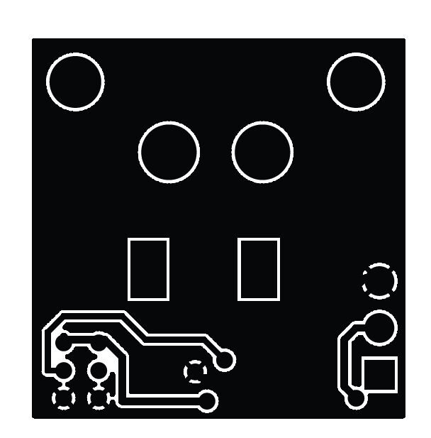
- PCB Dimensions 20.64 x 20.96 mm
Schematic
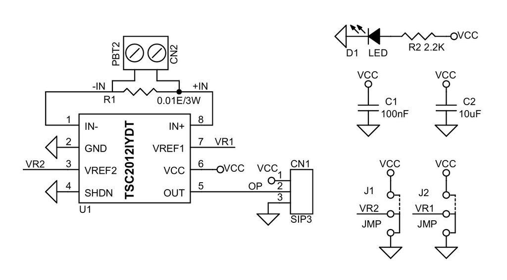
Connections
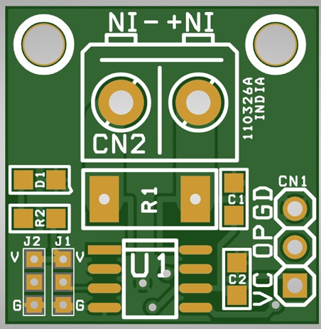
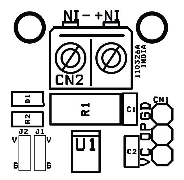
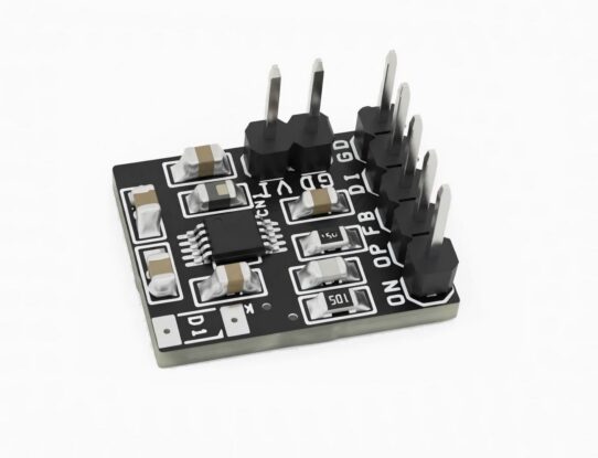
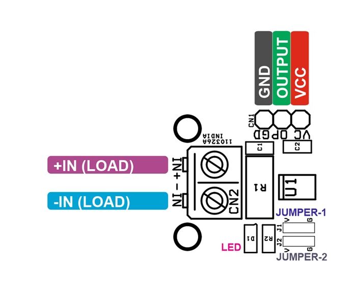
- CN1: Pin 1 = VCC, Pin 2 = Output, Pin 3 = GND
- CN2: Pin 1 = -IN (Load Current) , Pin 2 = +IN (Load Current)
- D1: Power LED
- J1: Jumper 1 = VREF 2 GND/VCC Selection
- J2: Jumper 2 = VREF 1 GND/VCC Selection
Part List
| NO. | QNTY. | REF. | DESC. | MANUFACTURER | SUPPLIER | SUPPLIER PART NO |
|---|---|---|---|---|---|---|
| 1 | 1 | CN1 | 3 PIN MALE HEADER PITCH 2.54MM | WURTH | DIGIKEY | 732-5316-ND |
| 2 | 1 | CN2 | 2 PIN SCREW TERMINAL PITCH 5.08MM | PHOENIX | DIGIKEY | 277-1247-ND |
| 3 | 1 | C1 | 100nF/50V CERAMIC SMD SIZE 0805 | YAGEO/MURATA | DIGIKEY | |
| 4 | 1 | C2 | 10uF/25V CERAMIC SMD SIZE 0805 | YAGEO/MURATA | DIGIKEY | |
| 5 | 1 | D1 | LED RED SMD | OSRAM | DIGIKEY | 475-1278-1-ND |
| 6 | 1 | J1, J2 | JMP-SOLDER TYPE | DIGIKEY | ||
| 7 | 1 | R1 | 0.01E/3W 1% SMD SIZE 2512 | BOURNS INC | DIGIKEY | CRA2512-FZ-R010ELFCT-ND |
| 8 | 1 | R2 | 2.2K 5% SMD SIZE 0805 | YAGEO/MURATA | DIGIKEY | |
| 9 | 1 | U1 | TSC2012IYDT | ST | DIGIKEY | 497-TSC2012IYDTCT-ND |
Unidirectional Operation
Unidirectional mode of operation allows the device to measure the current through a shunt resistor in one direction only. The output reference can be ground or Vcc and can be set by using Vref1 and Vref2 pins for adjustment.
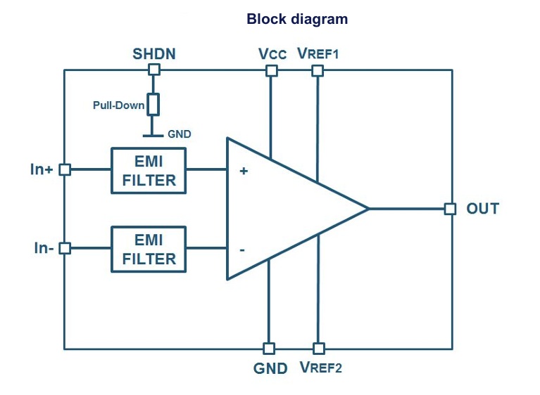
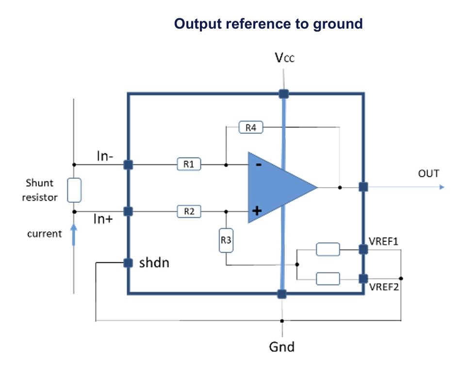
Ground Referenced (Jumper J1 and J2 Connected to GND)
In this configuration Vref1 pin and Vref2 pin are connected together to the ground. The output common mode voltage is then automatically set to GND when no current flows through the Rshunt resistance. This configuration allows the full-scale output in unidirectional mode. It allows a current to be measured as described in Output reference to ground.
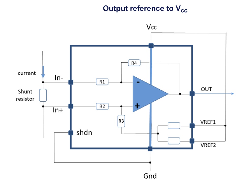
VCC Referenced (Jumper J1 and J2 Connected to VCC)
In this configuration Vref1 pin and Vref2 pin are connected together to the Vcc power supply. The output common mode voltage is then automatically set to Vcc voltage when no current flows through the Rshunt resistance. This configuration allows the full-scale output in unidirectional mode
Bidirectional operation
Jumper settings: (J1=VCC, J2=GND)
Bidirectional mode of operation allows the device to measure currents through a shunt resistor in two directions. The output reference can be set anywhere within the power supply range. If the output common mode voltage is set at mid-range, the full-scale current measurement range is equal in both directions. This is achieved by connecting one Vref pin to Vcc and the other Vref pin to GND as described by Figure. Split supply. It can be done as well connecting both Vref pins to Vcc / 2 voltage as described by Figure. External supply. In case the current measurement is not equal in both directions, user can set the output in a non-symmetrical configuration, adjusting Vref according to the user’s needs.
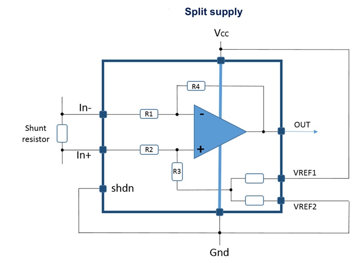
The great advantage of this configuration, is that the TSC2012 can be used in bidirectional mode with an output common mode voltage set at the middle of scale, with an accuracy of 0.1%, without any added external component or power supply. This configuration creates a midscale offset ratiometric to the power supply.
PCB View