
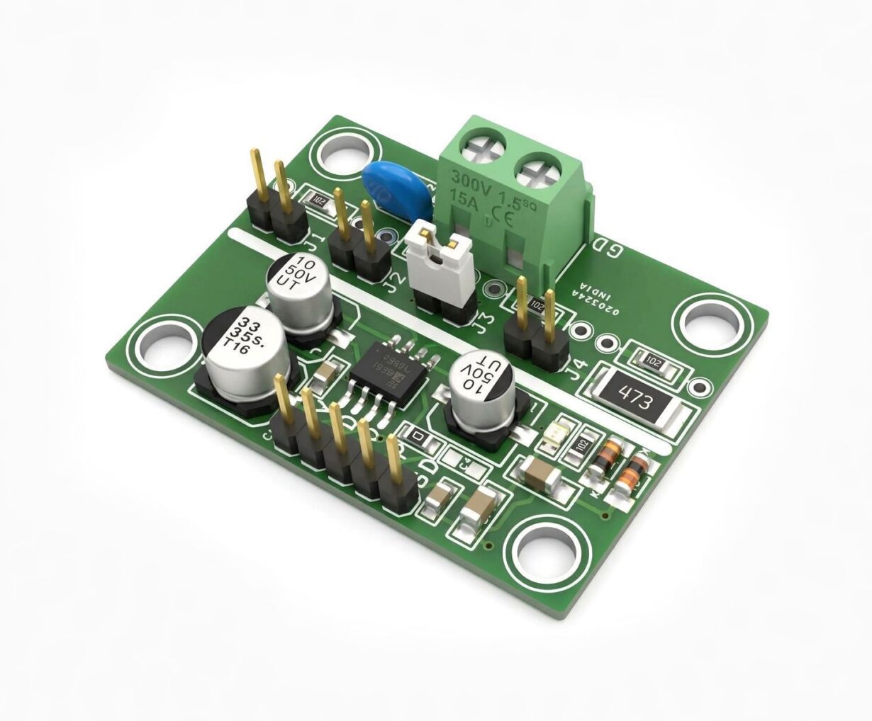
Introduction
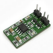
This is a low-cost, low-power True RMS-to-DC converter designed to provide accurate RMS measurements over a wide range of input waveforms. It can accurately measure complex signals, including variable-duty-cycle pulses and TRIAC (phase)-controlled sine waves.
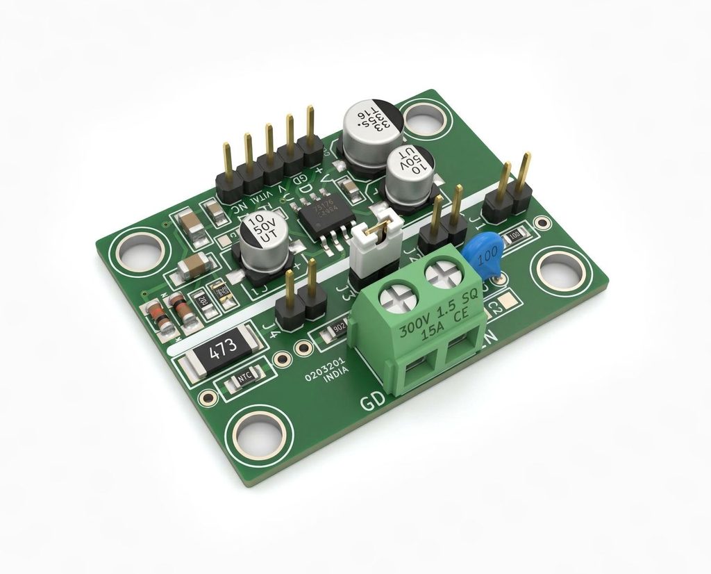
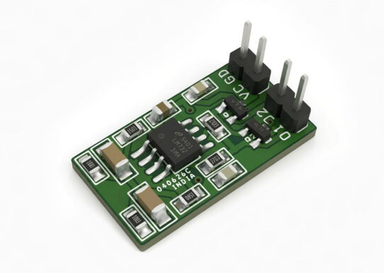
The converter is built around the AD736 True RMS-to-DC converter IC, providing high accuracy while maintaining low power consumption and a compact circuit design. Its low cost and small size make it an excellent solution for upgrading the performance of conventional non-RMS precision rectifier circuits in a wide range of measurement and instrumentation applications.
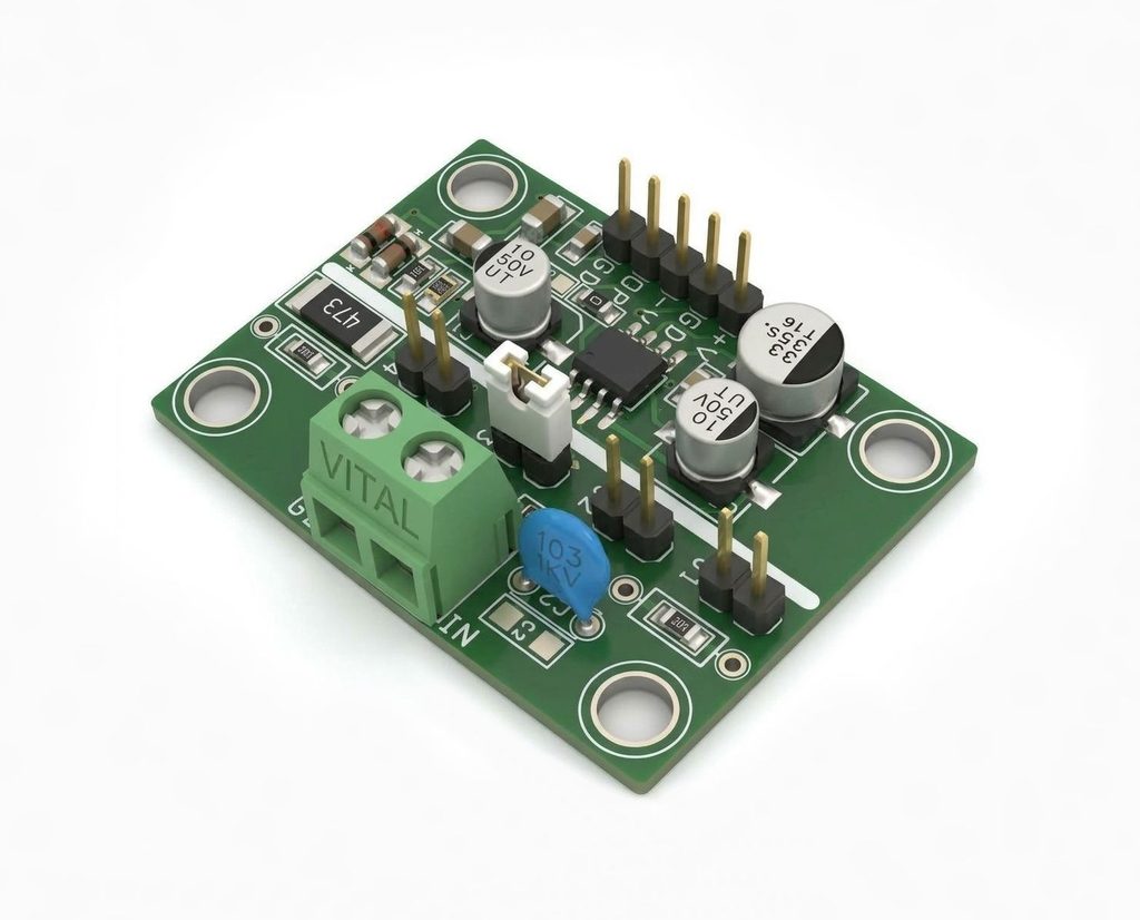
Compared with conventional rectifier-based circuits, the AD736-based design offers higher accuracy at an equal or lower overall cost. The AD736 provides a 1% reading accuracy bandwidth exceeding 10 kHz for input amplitudes ranging from 20 mV RMS to 200 mV RMS, while consuming only approximately 1 mW of power (Only Chip), LED draw 10mA.
Features
- Power Supply +/-5V DC (Dual 5V DC)
- Input Voltage Range 200mV, 2V, 20V, 200V
- Output 20 to 200mV DC
- Input 20mV to 200mV
- True RMS-to-DC conversion
- Low cost and low power consumption
- High measurement accuracy
- Supports complex and non-sinusoidal waveforms
- Measures variable-duty-cycle pulse signals
- Suitable for TRIAC phase-controlled sine waves
- 1% reading accuracy bandwidth exceeding 10 kHz*
- Input range: 20 mV RMS to 200 mV RMS*
- Compact design
- Ideal for replacing or upgrading precision rectifier circuits
- PCB Mounting Holes 4x4mm
- PCB Dimensions 43.18 x 31.75mm
Schematic
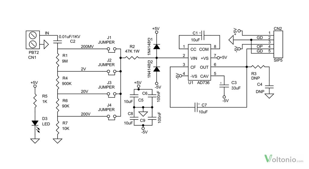
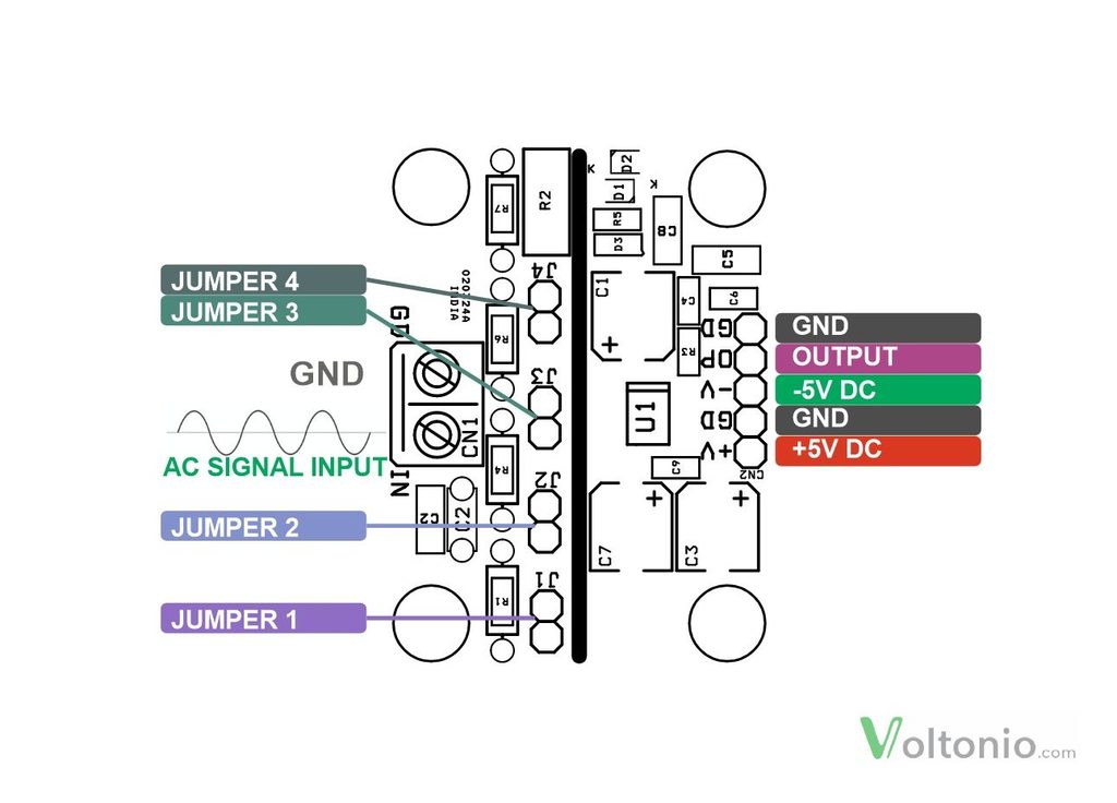
Connections
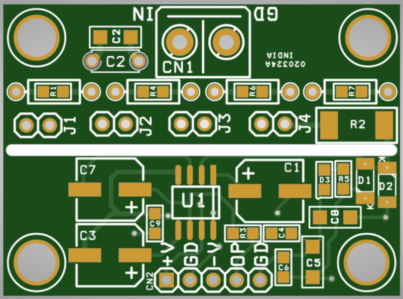
- CN1: Pin 1 = AC Signal Input, Pin 2 = GND
- CN2: Pin 1 = +5V DC, Pin 2 = GND, Pin 3 = -5V DC, Pin 4 = DC Voltage Output, Pin 5 = GND
- Jumpers: J1 = 200mV, J2 = 2V, J 3 = 20V, J4 = 200V (Input Voltage Range Selection)
- D3: Power LED
Part List
| NO. | QNTY. | REF. | DESC. | MANUFACTURER | SUPPLIER | SUPPLIER PART NO |
|---|---|---|---|---|---|---|
| 1 | REF | CN1 | 2 PIN SCREW TERMINAL PITCH 5.08MM | PHOENIX | DIGIKEY | 277-1247-ND |
| 2 | 1 | CN2 | 5 PIN MALE HEADER PITCH 2.54MM | WURTH | DIGIKEY | 732-5318-ND |
| 3 | 2 | C1,C5 | 10uF/25V ELECKTROLYTIC | NICHICON | DIGIKEY | 493-2185-1-ND |
| 4 | 1 | C2 | 0.01uF/1KV | VISHAY | DIGIKEY | BC5182-ND |
| 5 | 1 | C3 | 33uF/25V ELEKTROLYTIC | WURTH | DIGIKEY | 732-8434-1-ND |
| 6 | 2 | R3,C4 | DNP | |||
| 7 | 2 | C6,C9 | 100nF/50V CERAMIC SMD SIZE 0805 | YAGEO/MURATA | DIGIKEY | |
| 8 | 2 | D1,D2 | 1N4148 | MICROCHIP | DIGIKEY | 1N4148UR-1-ND |
| 9 | 1 | D3 | LED RED SMD SIZE 0805 | OSRAM | DIGIKEY | 475-1278-1-ND |
| 10 | 4 | J1,J2,J3,J4 | 2 PIN MALE HEADER PITCH 2.54MM | WURTH | DIGIKEY | 732-5315-ND |
| 11 | 1 | R1 | 9M/1% SMD SIZE 00805 | YAGEO/MURATA | DIGIKEY | |
| 12 | 1 | R2 | 47K 1W | YAGEO/MURATA | DIGIKEY | |
| 13 | 1 | R4 | 900K 1% SMD SIZE 0805 | YAGEO/MURATA | DIGIKEY | |
| 14 | 1 | R5 | 1K 5% SMD SIZE 0805 | YAGEO/MURATA | DIGIKEY | |
| 15 | 1 | R6 | 90K 1% SMD SZE 0805 | YAGEO/MURATA | DIGIKEY | |
| 16 | 1 | R7 | 10K 1% SMD SIZE 0805 | YAGEO/MURATA | DIGIKEY | |
| 17 | 1 | U1 | AD736 SOIC8 | ANALOG DEVICE | DIGIKEY | 505-AD736ARZ-ND |
| 18 | 2 | C7, C8 | 10uF/25V CERAMIC SMD SIZE 0805 | YAGEO/MURATA | DIGIKEY |
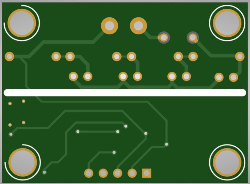
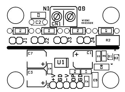
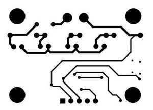
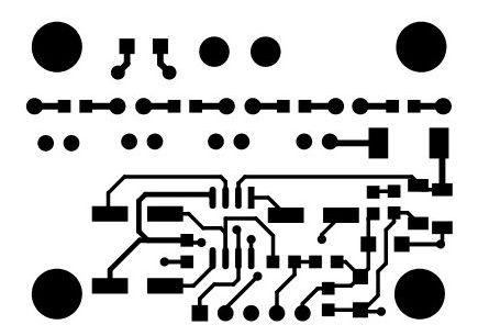
PCB View