
Introduction
The project uses the PCM5122 chip to convert digital signals into high-quality analog signals, providing excellent audio quality and stereo audio output. An ESP32, RP2350, or Raspberry Pi can be used as the host controller.
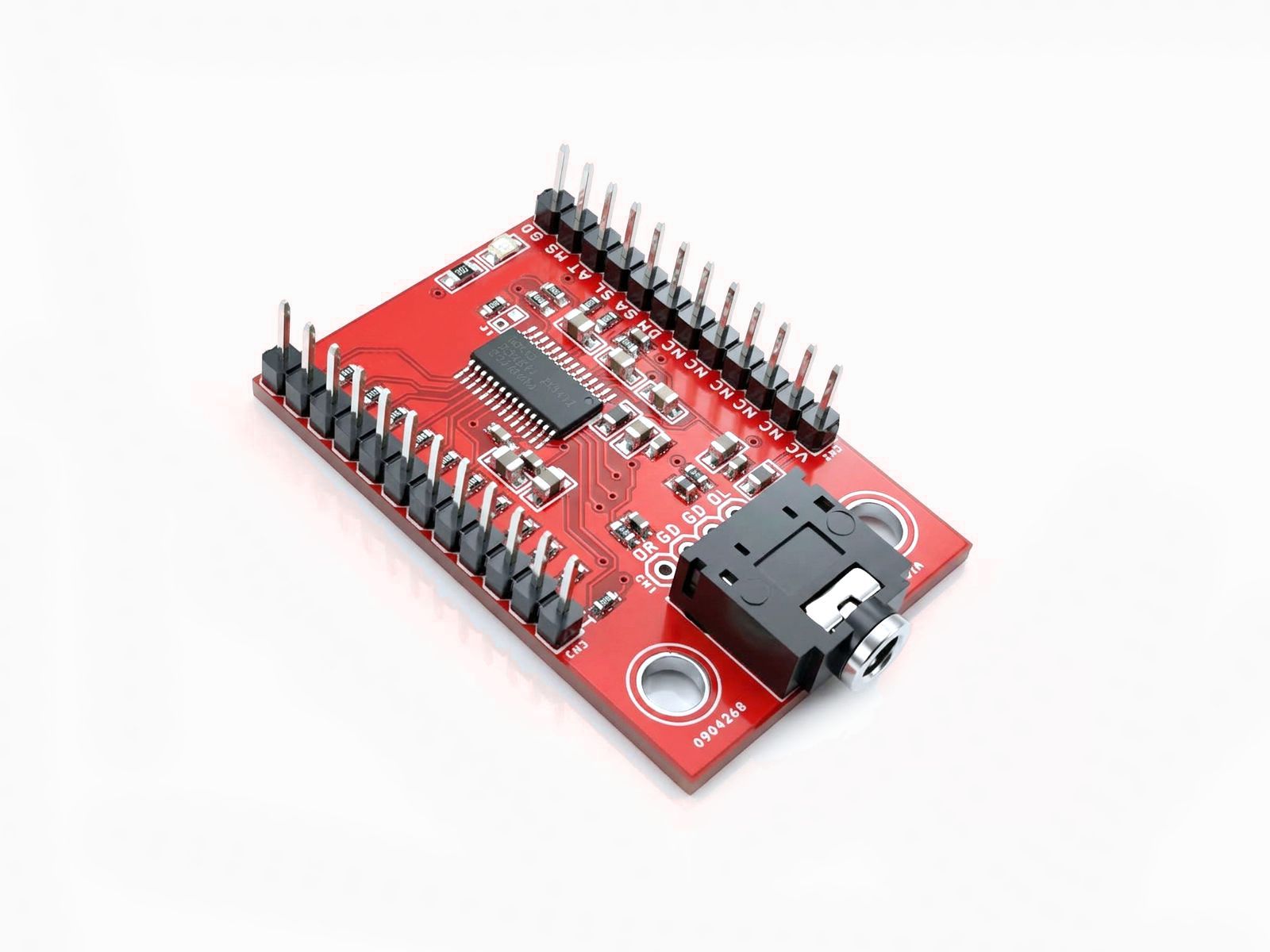
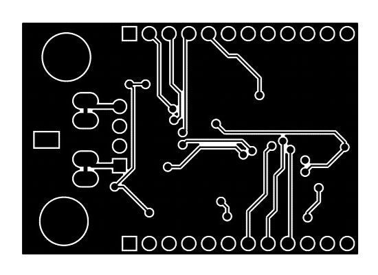
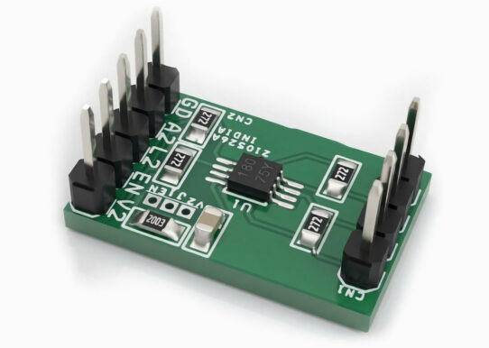
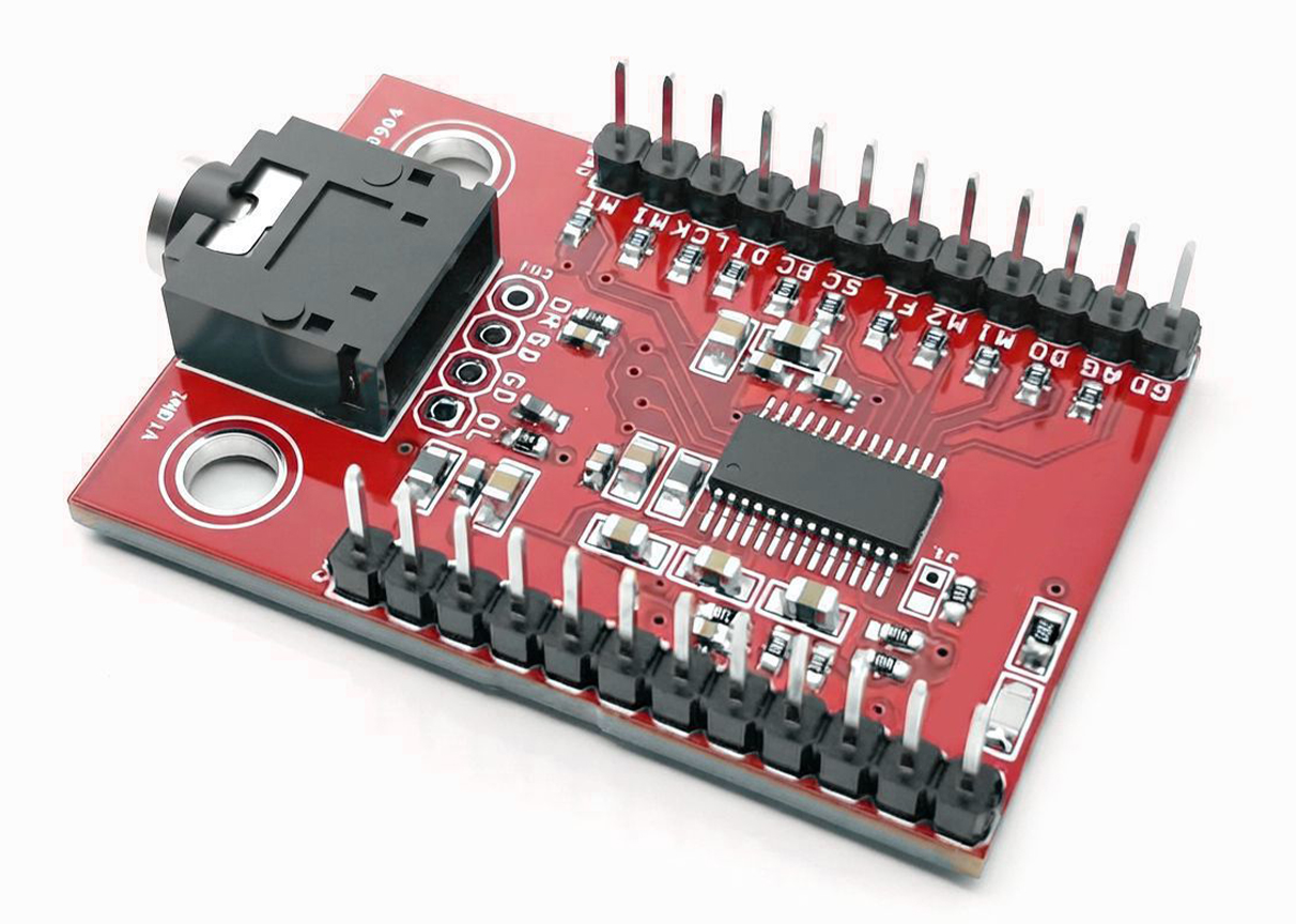
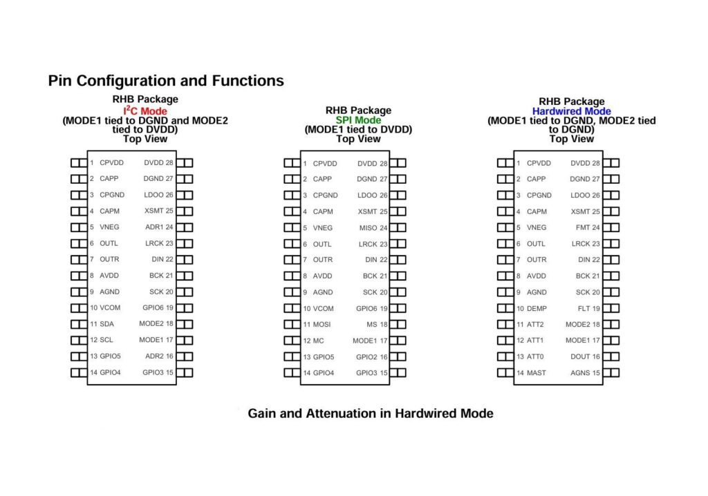
The breakout board provides access to all I/O pins through header connectors for easy interfacing. It supports three operating modes: I2C (I2S), SPI, and Hardware mode. Users should refer to the PCM5122 datasheet to configure the board according to their application requirements. Depending on the selected mode, certain components may need to be installed or left unpopulated. A stereo EP female socket is also provided for audio output.
Features
- Single Supply Operation: – 3.3-V Analog, 1.8-V or 3.3-V Digital
- Integrated Power-On Reset
- Automatic Power-Save Mode When LRCK and BCK are Deactivated
- Accepts 16-, 20-, 24-, and 32-Bit Audio Data
- PCM Data Formats: I2S, Left-Justified, Right Justified, TDM / DSP
- SPI or I2C Control
- Software or Hardware Configuration
- DAC to 384-kHz fS
- Market-Leading Low Out-of-Band Noise
- Selectable Digital-Filter Latency and Performance
- Integrated Negative Charge Pump
- Intelligent Muting System; Soft Up or Down Ramp and Analog Mute for 120-dB Mute SNR
- Integrated High-Performance Audio PLL With BCK Reference to Generate SCK Internally
- Accepts 16-, 20-, 24-, and 32-Bit Audio Data
- PCM Data Formats: I2S, Left-Justified, Right Justified, TDM / DSP
- PCB dimensions: 43.66 x 30.16 mm
Schematic
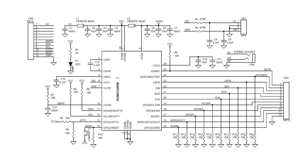
Connections
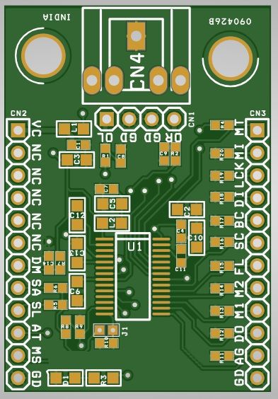
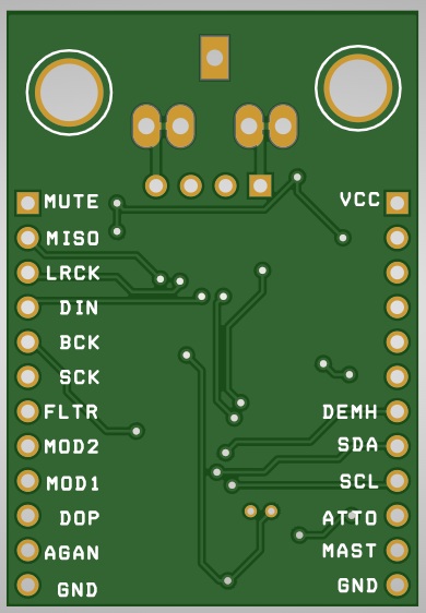
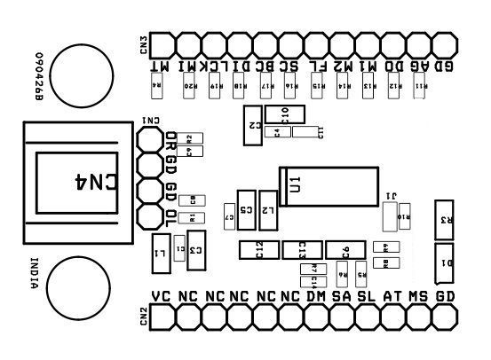
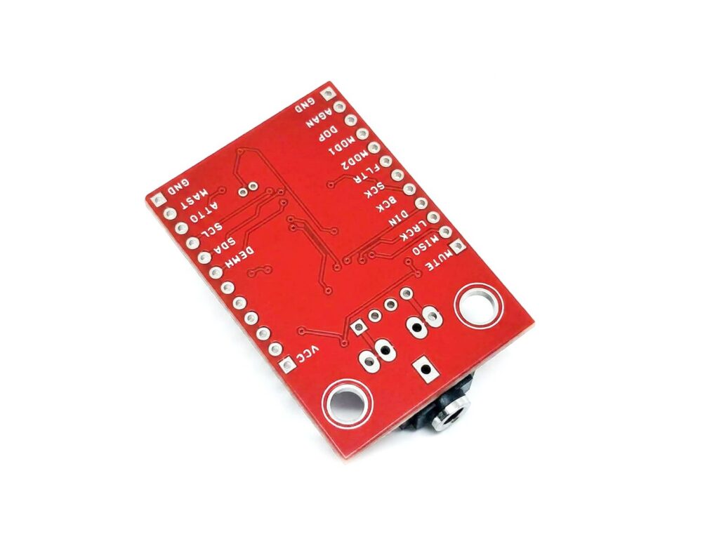
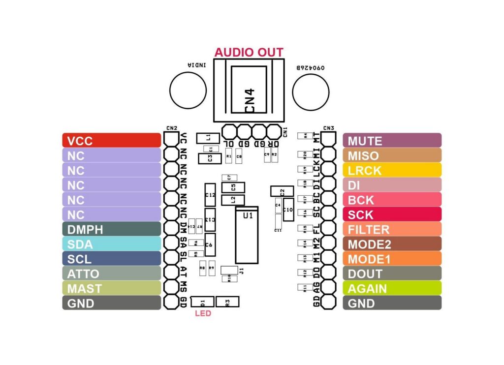
- CN1: Pin 1 = Audio Output Left Channel, Pin 2 = GND, Pin 3 = GND, Pin 4 = Audio Output Right Channel
- CN2: Pin 1 = VCC/3.3V, Pin 2,3,4,5,6 = Not Connected, Pin 7 = DMPH, Pin 8 = SDA, Pin 9 = SCL, Pin 10 = ATTO, Pin 11 = MAST, Pin 12 GND
- CN3: Pin 1 – Mute, Pin 2 = ADR1/MISO/FMT, Pin 3 = LRCK, Pin 4 = DIN, Pin 5 = BCK, Pin 6 = SCK, Pin 7 = Filter/GPIO6, Pin 8 = MODE 2. Pin 9 = Mode 1, Pin 10 = ADR2/GPIO2/DOUT, Pin 11 = AGAIN/GPIO3, Pin 12 = GND
- J1: Jumper Pull High = GPIO4/MAST
- D1: Power LED
Part List
| NO. | QNTY. | REF. | DESC. | MANUFACTURER | SUPPLIER | SUPPLIER PART NO |
|---|---|---|---|---|---|---|
| 1 | 1 | CN1 | 4 PIN MALE HEADER PITCH 2.54MM | WURTH | DIGIKEY | 732-5317-ND |
| 2 | 2 | CN2,CN3 | 12 PIN MALE HEADER PITCH 2.54MM | WURTH | DIGIKEY | 732-5323-ND |
| 3 | 1 | CN4 | STEREO SOCKET EP 3.5MM FEMALE | CUI AUDIO | DIGIKEY | CP1-3525N-ND |
| 4 | 5 | C1,C4,C7,C11,C14 | 100nF/25V CERAMIC SMD SIZE 0603 | YAGEO/MURATA | DIGIKEY | |
| 5 | 5 | C2,C3,C5,C6,C10 | 10uF/25V CERAMIC SMD SIZE 0805 | YAGEO/MURATA | DIGIKEY | |
| 6 | 2 | C8,C9 | 2.2nF/25V CERAMIC SMD SIZE 0805 | YAGEO/MURATA | DIGIKEY | |
| 7 | 2 | C12,C13 | 2.2uF/25V CERAMIC SMD SIZE 0805 | YAGEO/MURATA | DIGIKEY | |
| 8 | 1 | D1 | LED RED SMD SIZE 0805 | OSRAM | DIGIKEY | 475-1278-1-ND |
| 9 | 1 | J1 | 2 PIN MALE HEADER | WURTH | DIGIKEY | 732-5315-ND |
| 10 | 2 | L1,L2 | FERRITE BEAD 600OHM SMD SIZE 0805 | LAIRD | DIGIKEY | 240-2399-1-ND |
| 11 | 2 | R1,R2 | 470E 5% SMD SIZE 0603 | YAGEO/MURATA | DIGIKEY | |
| 12 | 1 | R3 | 1K 5% SMD SIZE 0805 | YAGEO/MURATA | DIGIKEY | |
| 13 | 17 | R4,R5,R6,R7,R8,R9,R10,R11,R12,R13,R14,R15,R16,R17,R18,R19,R20 | 10K 5% SMD SIZE 0603 | YAGEO/MURATA | DIGIKEY | |
| 14 | 1 | U1 | PCM5122PW | TI | DIGIKEY | 296-41605-5-ND |
| 15 | 1 | SHUNT FOR J1-JUMPER | SHUNT FOR J1 | SULLINS CONNECT | DIGIKEY | S9001-ND |
PCM5122 IC
2V RMS DIRECTPATH 112dB Audio Stereo DAC with PCM Interface and Fixed Audio Processing
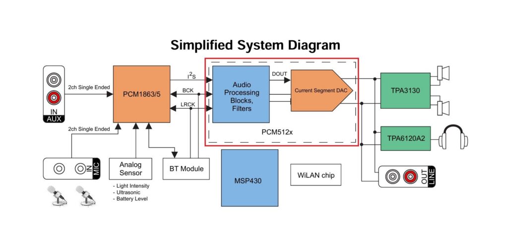
PCM5122 provides 2.1-VRSM ground-cantered output, which eliminate DC-Blocking capacitors on output, The integrated line driver surpasses all other charge pump-based line drivers by supporting loads down to 1 kΩ. By supporting loads down to 1 kΩ, the PCM512x can essentially drive up to 10 products in parallel (LCD TV, DVDR, AV receivers, and so forth). The integrated PLL on the device removes the requirement for a system clock (commonly known as master clock), allowing a 3-wire I2S connection, along with reducing system EMI.
The integrated PLL on the device provided adds the flexibility to remove the system clock (Commonly known as master clock), allowing a 3-wire I2S connections and reducing system EMI. In addition, the PLL is completely programmable, allowing the device to become the I2S clock master and drive a DSP serial port as a slave. The PLL also accepts a non-standard clock (up to 50Mhz) as source to generate the audio related clock (for example, 24.576Mhz)
Power sense undervoltage protecting utilizes a two-level mute system. Upon clock error or system power failure, the device digitally attenuates the data (or last knows good data) and then mutes the analog circuit. PCM5122 devices offers up to 20dB of lower out-of-band noise, reducing EMI and aliasing in downstream amplifiers/ADCs. The PCM5122 project accept industry-standard audio data formats with 16-bit to 32Bit data. Sample rates up to 384Khz are supported.
PCB View