
Introduction
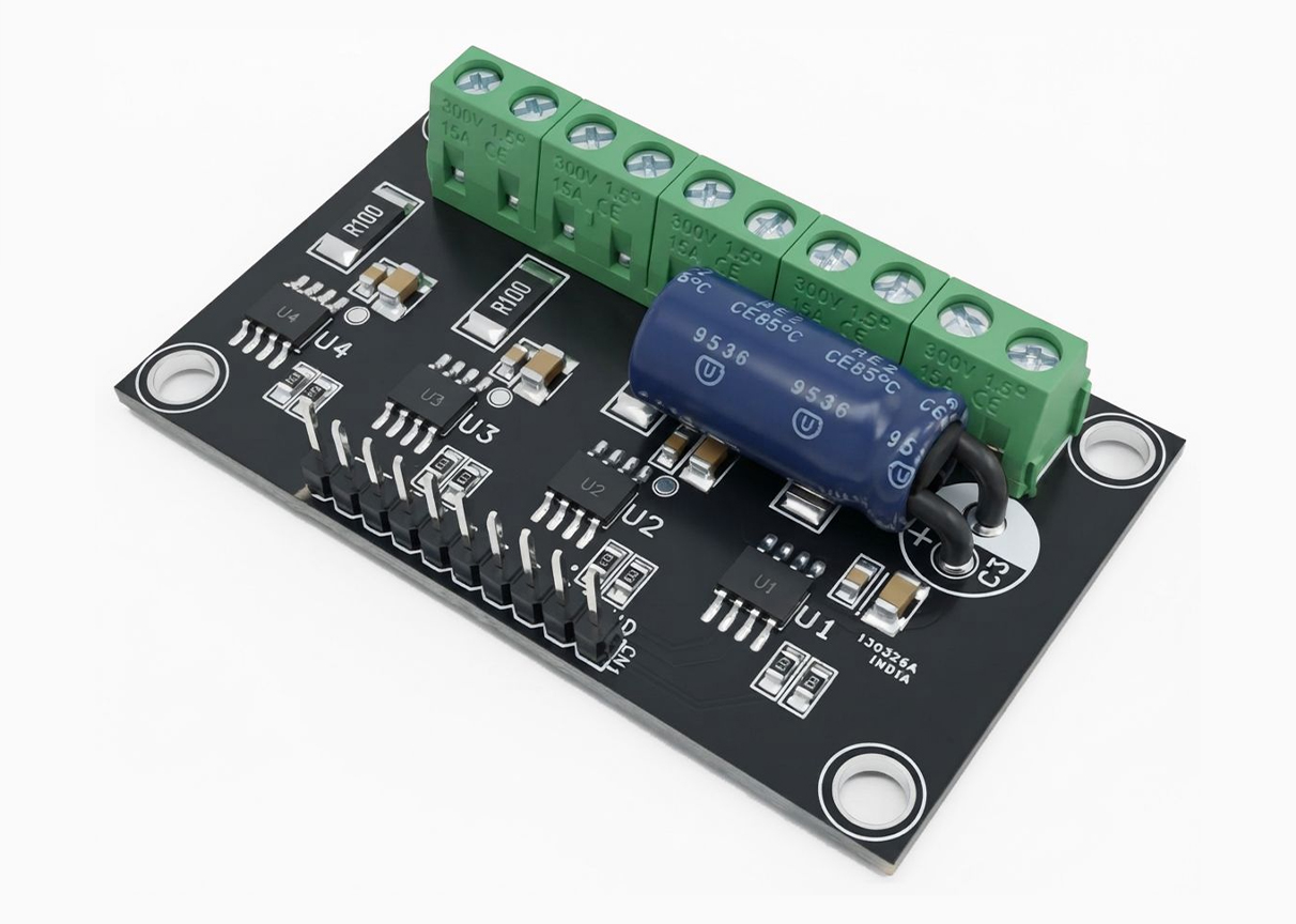
This project presents an ideal solution for robots requiring control of up to four DC brushed motors. It integrates four independent 3.5 A motor driver channels, making it well-suited for multi-motor applications such as 4-wheel-drive robot cars and other robotic platforms that require multiple motors to operate simultaneously. The four-channel design allows each motor to be controlled separately, providing a practical solution for multi-motor robotic systems.
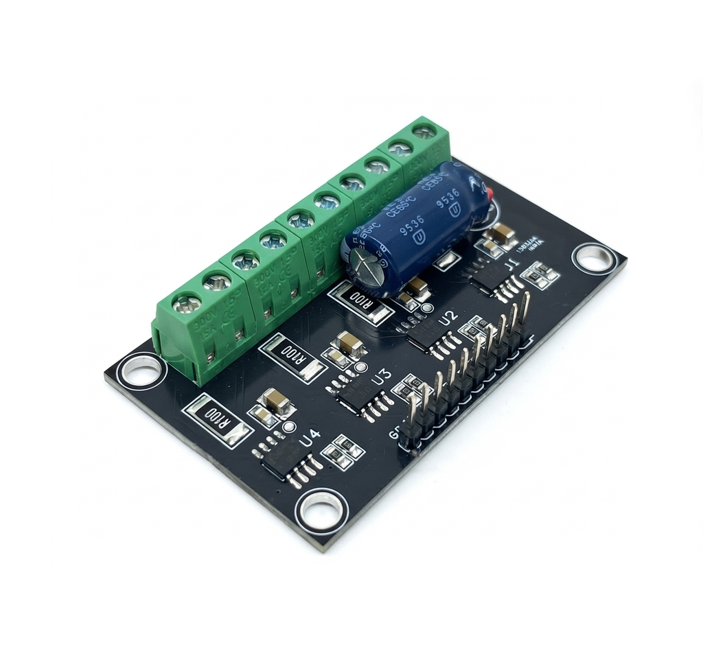
The system supports both direct PWM control and PWM-based constant current control, providing flexibility in motor operation and power management. Direct PWM control can be used for standard motor speed control, while the constant current control mode helps regulate the motor current for more controlled operation. The design is intended to provide reliable motor control while maintaining low power consumption, making it suitable for various battery-powered robotic applications.
Features
- Single power supply 8-40V DC (up to 40 V rated voltage)
- Continuous output current: 3.5 A per channel
- Peak output current: 6 A per channel
- Forward, Reverse, Brake, and high-impedance (open) modes
- Direct PWM control
- PWM constant current control (current limiting function)
- Built-in spike noise suppression
- Thermal shutdown protection
- Overcurrent protection
- Undervoltage lockout (UVLO)
- 4x 4 mm Mounting Holes
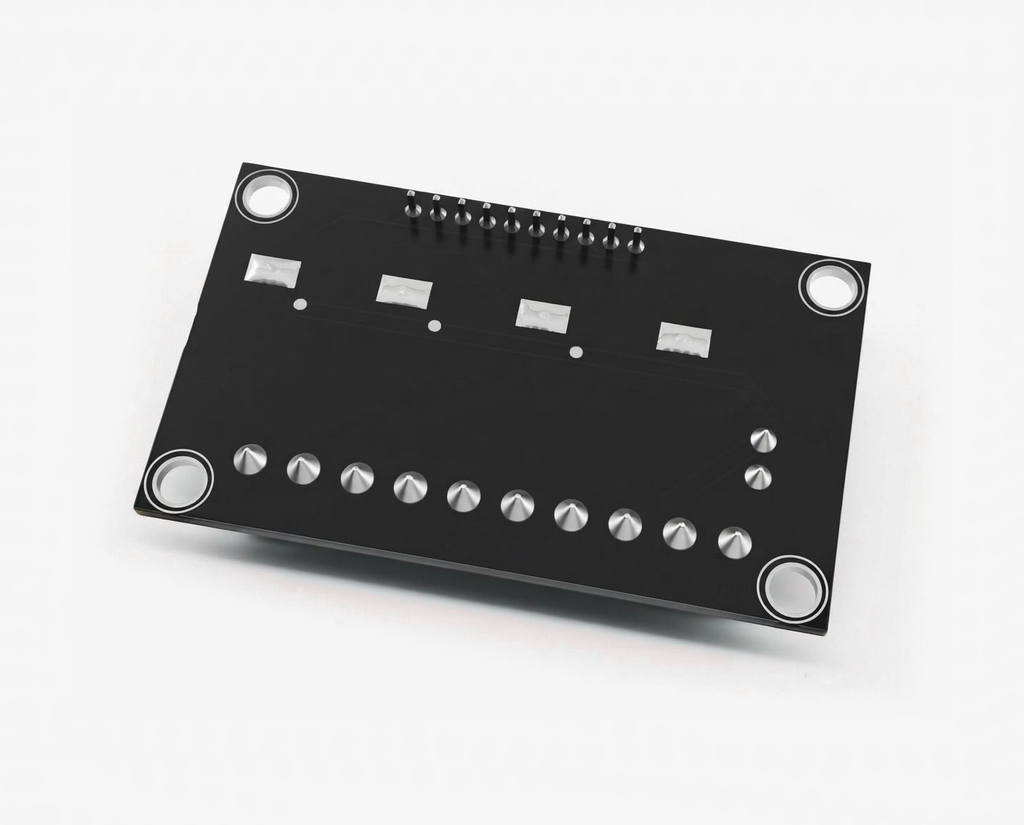
- PCB Dimensions 64.10 x 38.10 mm
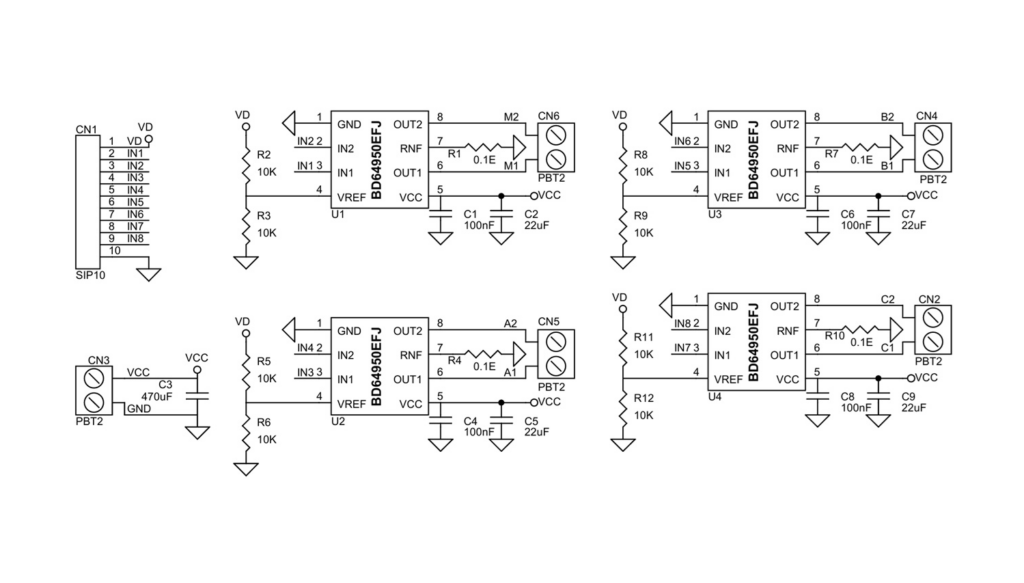
Schematic
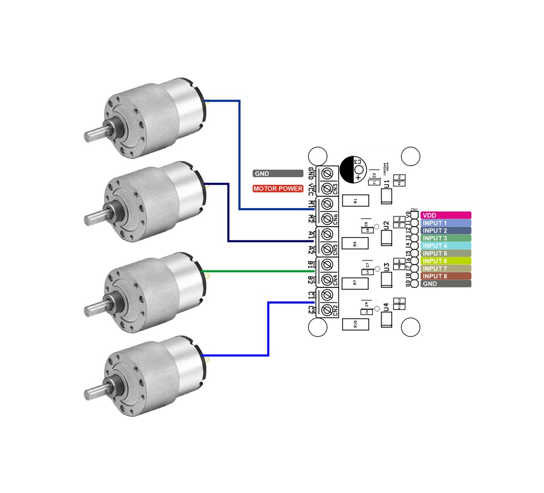
Connections
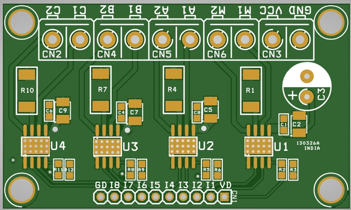
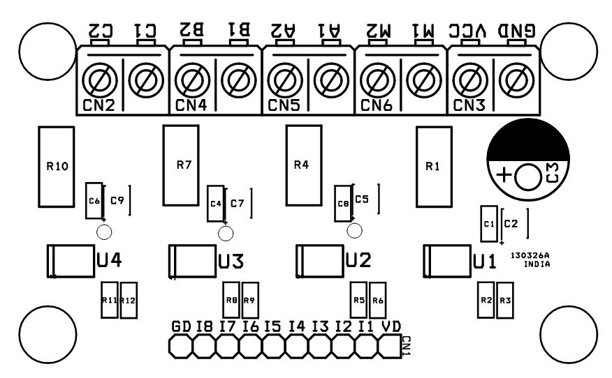
- CN1: Pin 1 = VDD 5V DC, Pin 2 = Input 2, Pin 3 = Input 1, Pin 4 = Input 4, Pin 5 = Input 3, Pin 6 = Input 6, Pin 7 = Input 5, Pin 8 = Input 8, Pin 9 = Input 7, Pin 10 = GND
- CN2: Pin 1 = M2, Pin 2 = M1 (Motor 1)
- CN4: Pin 1 = A2, Pin 2 = A1 (Motor 2)
- CN5: Pin 1 = B2, Pin 2 = B1 (Motor 3)
- CN6: Pin 1 = C2, Pin 2 = C1 (Motor 4)
- CN3: Pin 1 = Motor Supply 8V to 40V DC, Pin 2 = GND
Part List
| NO. | QNTY. | REF. | DESC. | MANUFACTURER | SUPPLIER | SUPPLIER PART NO |
|---|---|---|---|---|---|---|
| 1 | 1 | CN1 | 10 PIN MALE HEADER PITCH 2.54MM | WURTH | DIGIKEY | 732-2670-ND |
| 2 | 5 | CN2,CN3,CN4,CN5,CN6 | 2 PIN SCREW TERMINAL PITCH 5.08MM | PHOENIX | DIGIKEY | 277-1247-ND |
| 3 | 4 | C1,C4,C6,C8 | 100nF/50V CERAMIC SMD SIZE 0805 | YAGEO/MURATA | DIGIKEY | |
| 4 | 4 | C2,C5,C7,C9 | 22uF/50V CERAMIC SMD SIZE 1210 | YAGEO/MURATA | DIGIKEY | |
| 5 | 1 | C3 | 470uF/50V ELECTROLYTIC | PANASONIC | DIGIKEY | P5185-ND |
| 6 | 4 | R1,R4,R7,R10 | 0.1E/3W 1% SMD SIZE 2512 | BOURNS INC | DIGIKEY | CRA2512-FZ-R100ELFCT-ND |
| 7 | 8 | R2,R3,R5,R6,R8,R9,R11,R12 | 10K 5% SMD SIZE 0805 | YAGEO/MURATA | DIGIKEY | |
| 8 | 4 | U1,U2,U3,U4 | BD64950EFJ SOIC | ROHM | DIGIKEY | 846-BD64950EFJ-E2CT-ND |
H-Bridge Outputs
Output pin: OUT1, OUT2
Motor’s drive current is flowing in it, so please connect it in such a way that the wire is thick & short and has low impedance. It is also effective to add a Schottky diode if output has great positive or negative fluctuation when large current is applied. For example, a counter electromotive voltage etc. is great.
Moreover, there is a built-in clamp component in the output pin to prevent electrostatic destruction. If sudden pulse or surge voltage of more than the maximum absolute rating is applied, the clamp component operates which can result to destruction. Please be sure to not exceed the maximum absolute rating.
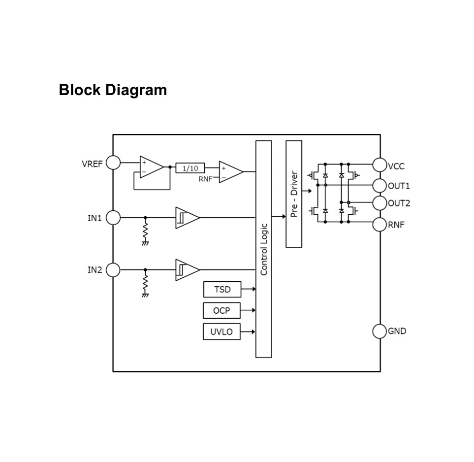
Current Sensing
RNF Connection
A 0.1 Ω current-sense resistor is used for PWM constant-current control and helps prevent the current from exceeding the absolute maximum rating.
Current Limit
VREF Setting
This pin is used to set the current limit value for PWM constant-current control or peak current limiting. The current limit is determined by the VREF voltage and the current sensing resistors R1, R4, R7, and R10.

The constant current value can be adjusted using the resistor divider networks:
- R2, R3
- R5, R6
- R8, R9
- R11, R12
The VREF input range is 0V to 3V. By default, VREF is set to 2.5V when VD = 5V.
The minimum current, which can be controlled by VREF voltage, is determined by motor coil’s L & R values and minimum ON time. There is a minimum ON time in PWM drive.
Direct PWM Control
This series can drive motors by IN1 and IN2 input directly from the microcomputer (up to 5 μs pulse width). SLOW DECAY can be used for DECAY mode.
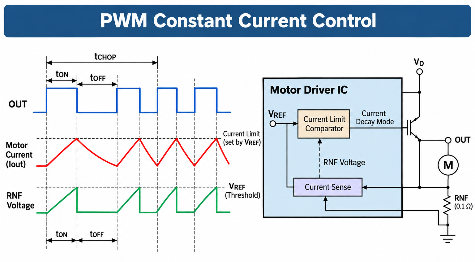
PWM Constant Current Control
This function can limit the peak current or switching current in driving DC brush motor.
1. Current Control Operation
When the output transistor is turned on, the output current increases. The output current is converted to voltage due to the connected external resistance to the RNF pin. When the voltage on the RNF pin reaches the voltage value set by the VREF input voltage, the current limit comparator operates and enters current decay mode. Output turns on again after fixed off time. The process repeats itself with chopping period (tCHOP).
2.Cancel Time (Fixed in Internal Circuit)
In order to avoid misdetection of current detection comparator due to RNF spike noise that may occur when the output turns on, the IC has the minimum on time tONMIN (Cancel Time). The current detection is invalid from the output transistor turned on to 3.0 μs (Typ). This allows for constant-current drive without the need for an external filter.
3.Current Limit
Maximum value of current limit can be set by VREF voltage and current-detecting resistor (RNF resistor). The transconductance function is approximated by the maximum value of current limit (ITripMAX).
Protection Circuits
Thermal Shutdown (TSD)
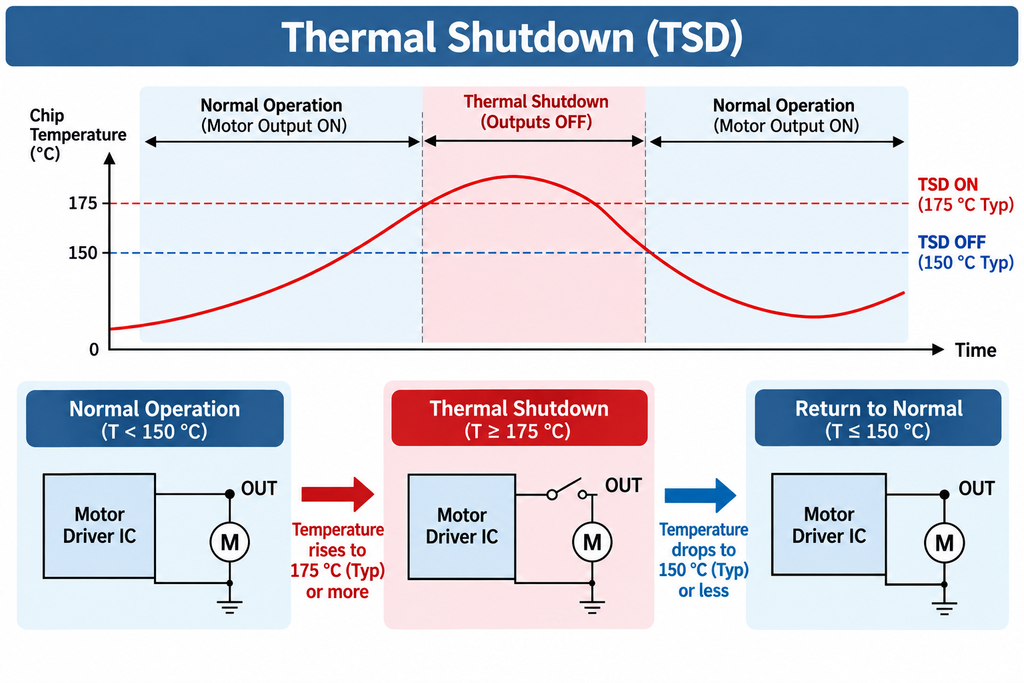
This IC has a built-in thermal shutdown circuit for thermal protection. When the IC’s chip temperature rises 175 °C (Typ) or more, the motor output becomes open. Also, when the temperature returns to 150 °C (Typ) or less, it automatically returns to normal operation. However, even when TSD is in operation, if heat is continued to be added externally, heat overdrive can lead to destruction.
Over Current Protection (OCP)
This IC has a built-in over current protection circuit as a provision against destruction when the motor outputs are shorted each other or VCC-motor output or motor output-GND is shorted. This circuit puts the motor output to OPEN condition for 400 µs (Typ) when the regulated current flows for 2 μs (Typ) and then returns. The over current protection circuit’s only aim is to prevent the destruction of the IC from irregular situations such as motor output shorts, and is not meant to be used as protection or security for the set. Therefore, sets should not be designed to take into account this circuit’s functions. After OCP operating, if the power is turned on again in an abnormal state, then OCP operates repeatedly and the IC may generate heat or otherwise deteriorate. When the L value of the wiring is great due to the wiring being long, the motor outputs are shorted each other or VCC-motor output or motor output-GND is shorted, if the output pin voltage jumps up and the absolute maximum values can be exceeded after the over current has flowed, there is a possibility of destruction. Also, when current which is the output current rating or more and the OCP detection current or less flows, the IC can heat up to Tjmax = 150 °C exceeds and can deteriorate, so current which or more the output rating should not be applied.
Under Voltage Lock Out (UVLO)
This IC has a built-in under voltage lock out function to prevent false operation such as IC output during power supply under voltage is low. When the applied voltage to the VCC pin goes 5 V (Typ) or less, the motor output is set to open. This switching voltage has a 1 V (Typ) hysteresis to prevent false operation by noise etc.
Protects against malfunction when power supply is disconnected (Ghost Supply Prevention Function)
If a control signal is input when there is no power supplied to this IC, there is a function which prevents a malfunction where voltage is supplied to power supply of this IC or other IC in the set via the electrostatic destruction prevention diode from these input pins to the VCC. Therefore, there is no malfunction of the circuit even when voltage is supplied to these input pins while there is no power supply.
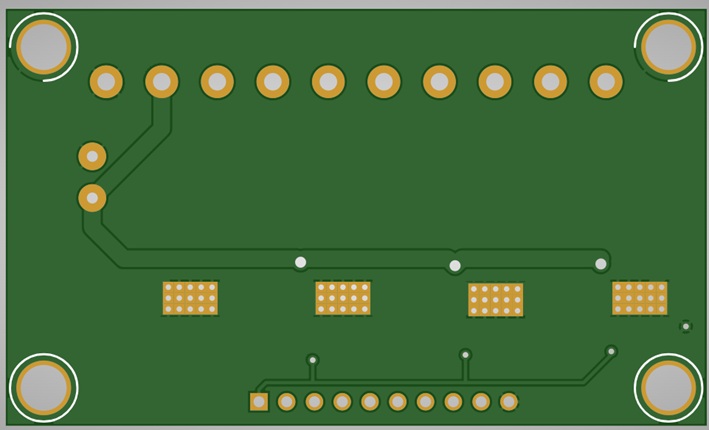
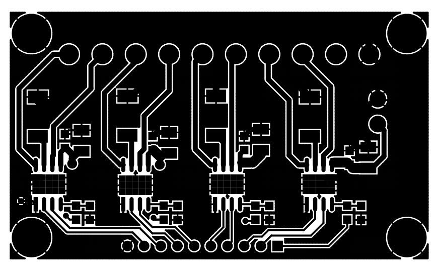
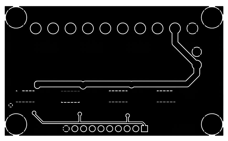
PCB View