
Introduction
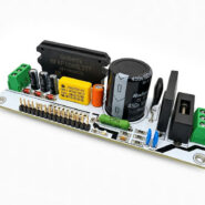
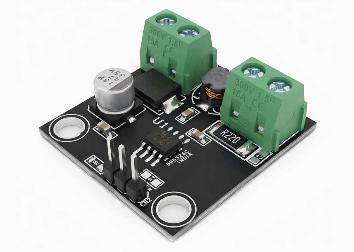
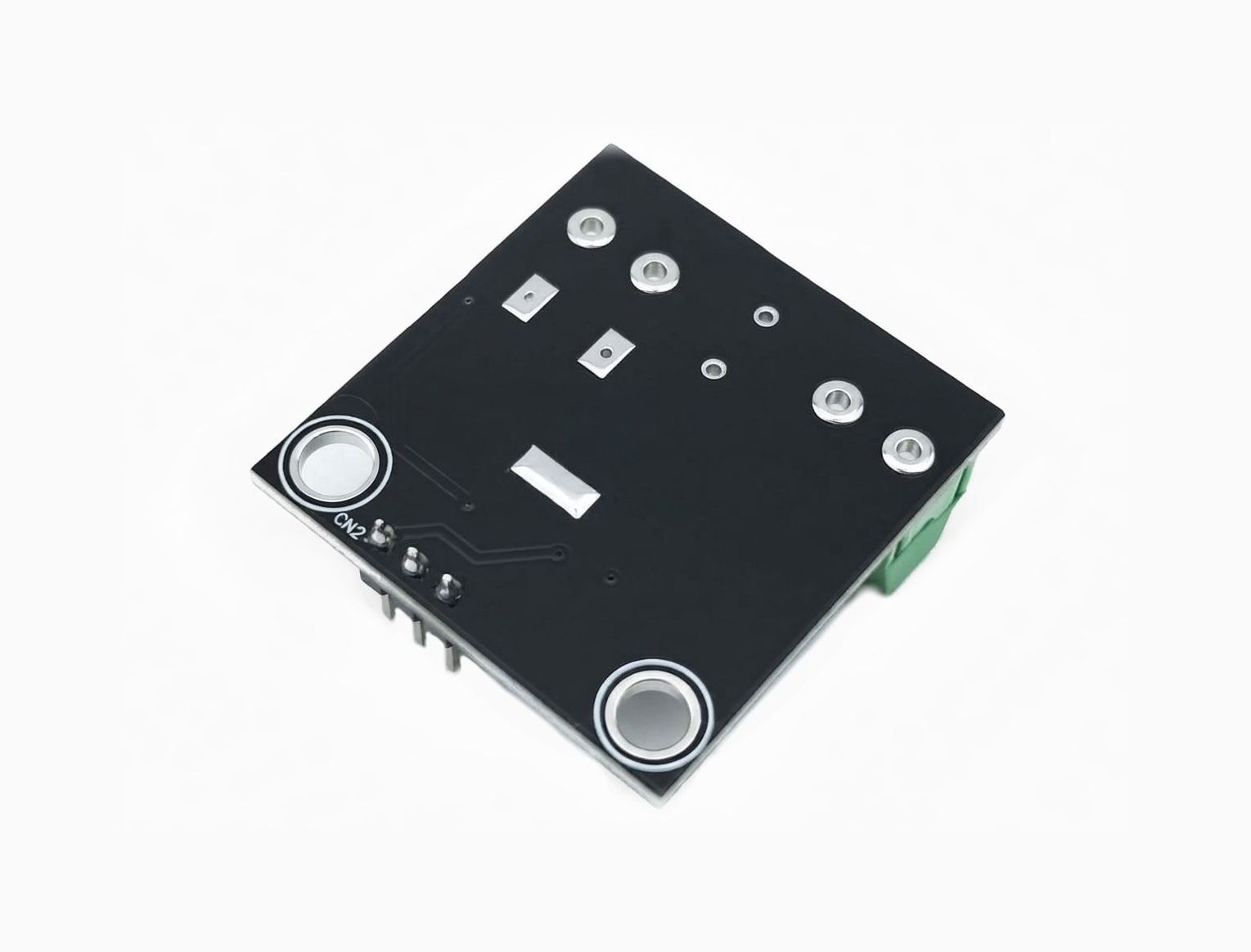
Project presented here is a automotive-grade, constant-current PWM dimmable buck regulator LED driver. Project is based on A6213 chip, which is provides constant current output to drive high power LEDs. It integrates a high side N channel DMOS switch for DC-DC step down conversion. A true average current is output using a cycle-by-cycle, controlled on-time method.
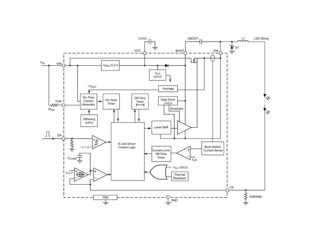
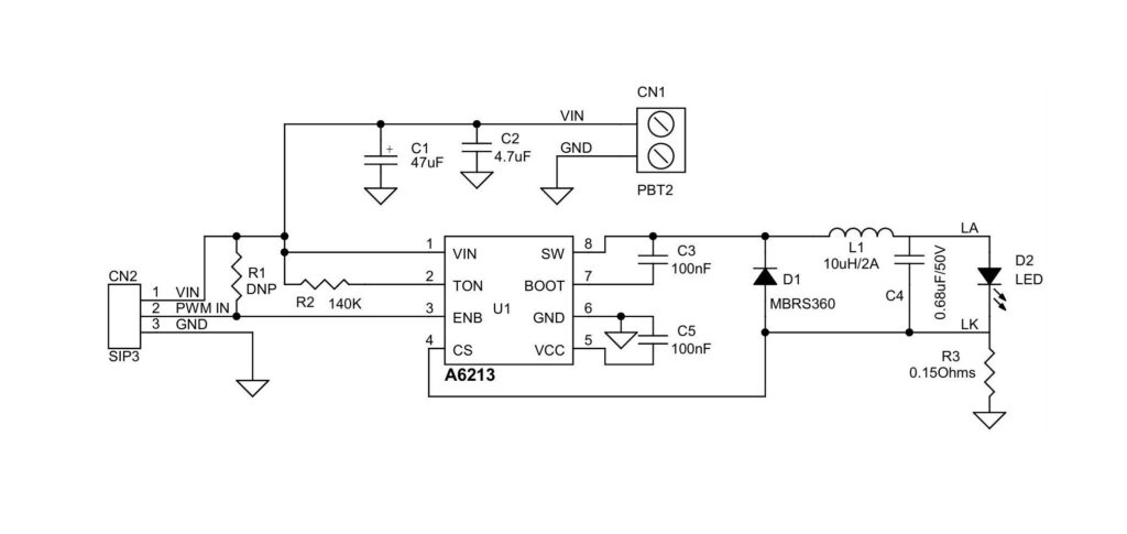
Output current is user selectable by external current sense resistor. Output voltage is automatically adjusted to drive various numbers of LEDs in single string, this ensures the optimal system efficiency. LED dimming is accomplished by a direct logic input pulse-width-modulation (PWM) signal at the enable pin. Project is capable to drive 15V LED string at 1.3A (Set by Rsense, R3, 0.15Ohm), Switching frequency is 500Khz, as set by R2, A 0.68uF ceramic capacitor is added across the LED string to reduce the ripple current trough the LEDs.
Features
- Supply 24V to 48V DC
- True Average Output Current 1.3A
- Capable of Driving 15V LED string
- Cycle By Cycle Current Limit
- PWM Frequency 100Hz to 2Khz TTL Input
- Dimming Via Direct PWM input (1% to 99% Duty Cycle)
- Internal Control Loop Compensation
- Undervoltage Lockout (UVLO) and Thermal Shutdown Protection
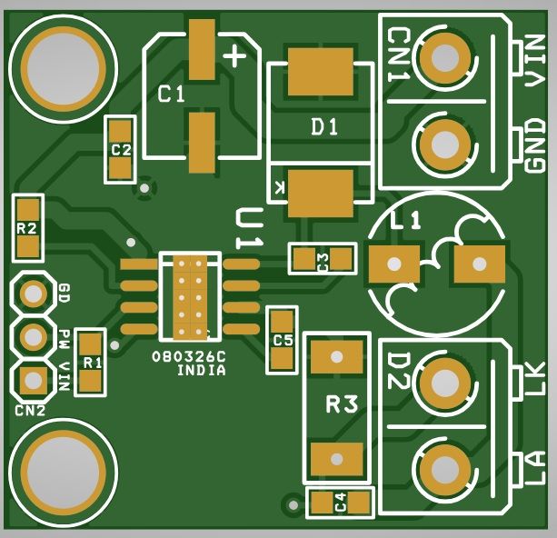
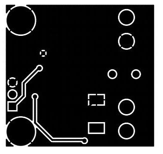
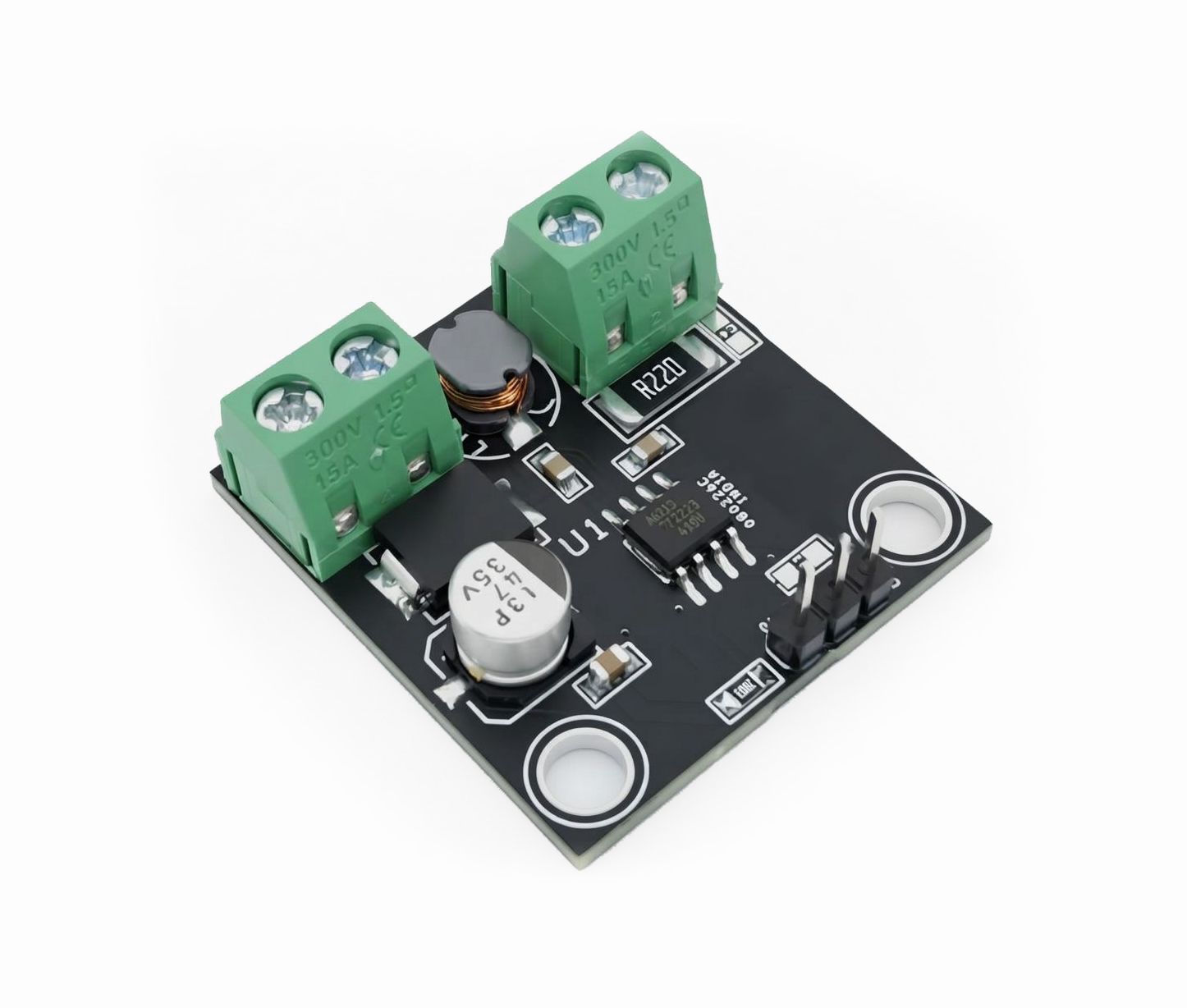
- 4 x 3 mm PCB Mounting Holes
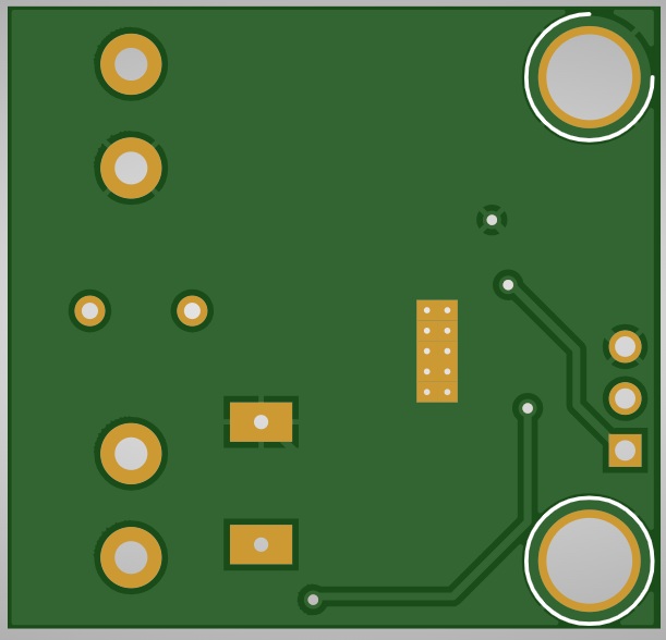
- PCB Dimensions 31.91 x 30.48 mm
Schematic
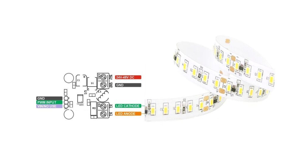
Connections
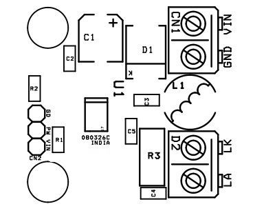
- CN1: Pin 1 = VIN 24 to 48V DC, Pin 2 = GND
- CN2: Pin 1 – Vin (No Use), Pin 2 PWM Input Frequency 100Hz to 2Khz, Duty Cycle 1% to 99%, Pin 3 = GND
- D2: LED String, Pin 1 = LED Anod, Pin 2 = LED Cathode
Part List
| NO. | QNTY. | REF. | DESC. | MANUFACTURER | SUPPLIER | SUPPLIER PART NO |
|---|---|---|---|---|---|---|
| 1 | 1 | CN1 | 2 PIN SCREW TERMINALS PITCH 5.08MM | PHOENIX | DIGIKEY | 277-1247-ND |
| 2 | 1 | CN2 | 3 PIN MALE HEADER PITCH 2.54MM | WURTH | DIGIKEY | 732-5316-ND |
| 3 | 1 | C1 | 47uF/50V ELECTROLYTIC | NICHICON | DIGIKEY | 493-2225-1-ND |
| 4 | 1 | C2 | 4.7uF/50V CERAMIC SMD SIZE 0805 | YAGEO/MURATA | DIGIKEY | |
| 5 | 2 | C3,C5 | 100nF/50V CERAMIC SMD SIZE 0805 | YAGEO/MURATA | DIGIKEY | |
| 6 | 1 | C4 | 0.68uF/50V CERAMIC SMD SIZE 0805 | YAGEO/MURATA | DIGIKEY | |
| 7 | 1 | D1 | MBRS360 | ON SEMI | DIGIKEY | MBRS360T3GOSCT-ND |
| 8 | 1 | D2 | 2 PIN SCREW TERMINALS PITCH 5.08MM | PHOENIX | DIGIKEY | |
| 9 | 1 | L1 | 10uH/2.5A (8X8MM) | BOURNS INC | DIGIKEY | SRN6045-100MCT-ND |
| 10 | 1 | R1 | DNP | |||
| 11 | 1 | R2 | 140K 1% SMD SIZE 0805 | YAGEO/MURATA | DIGIKEY | |
| 12 | 1 | R3 | 0.15Ohms/2W 1% SMD SIZE 2512 | BOURNS INC | DIGIKEY | CRM2512-FX-R150ELFCT-ND |
| 13 | 1 | U1 | A6213 SOIC8 | ALLEGRO | DIGIKEY | 620-1480-1-ND |
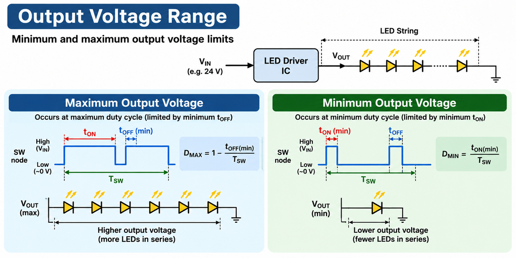
Output Voltage Range
Minimum and maximum output voltage limits
For a given input voltage, the maximum output voltage depends on the switching frequency and minimum tOFF. For example, if tOFF(min) = 150 ns and fSW = 1 MHz, then the maximum duty cycle is 85%. So for a 24 V input, the maximum output is 20.3 V. This means up to 6 LEDs can be operated in series, assuming Vf = 3.3 V or less for each LED. The minimum output voltage depends on minimum tON and switching frequency. For example, if the minimum tON = 150 ns and fSW = 1 MHz, then the minimum duty cycle is 15%. That means with VIN = 24 V, the minimum VOUT = 3.2 V (one LED). To a lesser degree, the output voltage is also affected by other factors such as LED current, on-resistance of the high-side switch, DCR of the inductor, and forward drop of the low-side diode.
PWM Dimming Ratio
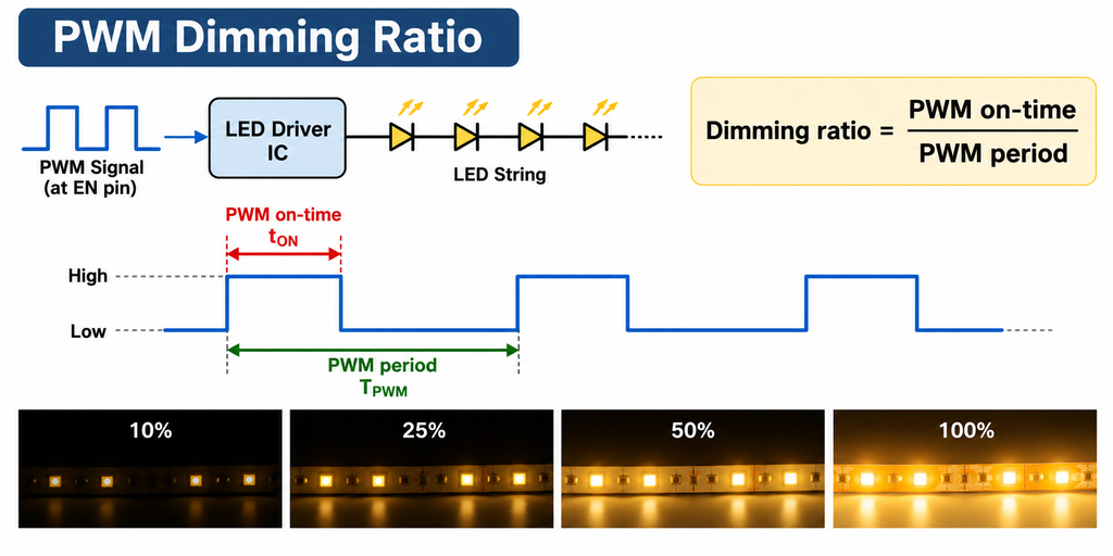
The brightness of the LED string can be reduced by adjusting the PWM duty cycle at the EN pin as follows:
Dimming ratio = PWM on-time / PWM period
For example, by selecting a PWM period of 5 ms (200 Hz PWM frequency) and a PWM on-time of 50 µs, a dimming ratio of 1% can be achieved. In an actual application, the minimum dimming ratio is determined by various system parameters, including: VIN, VOUT, inductance, LED current, switching frequency, and PWM frequency. As a general guideline, the minimum PWM on-time should be kept at 50 µs or longer. A shorter PWM on-time is acceptable under more favorable operating conditions.
PCB View